
SLIDE 1
If Ia Ia torque armature mmf ~ Ia ~ If field flux T = k f Ia
- a = k
f r Ia Ra V +
- +
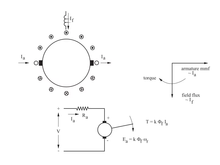
Ia Ia armature mmf ~ Ia torque field flux ~ If + Ra + Ia T - - PowerPoint PPT Presentation
If Ia Ia armature mmf ~ Ia torque field flux ~ If + Ra + Ia T = k f Ia V a = k - f r - STATOR Rr Ld FIELD + + + 3 phase V Id - C S I S M Vr Vi 50 Hz - - If r w Vr Rotor position
+
Vs j Lml
+
E j Lr
s Er Is
I Er E Ir Im r m jXr r I (a) (b)
+
Vs j Lm
+
Er . Lm Lr Rr s Lm Lr 2 . j Ls=j L s
Is Vs Is Is rs E I r =j m s
L2 r j Xs s
Rs s I ( r=-Lm s ) I I Lr
(a) (b)
3 phase 50 Hz ia w ib w ic w
CRPWM
Transformation from synchronous to stator reference Stator
IM
torque reference flux reference (Isq w ) (Isd w ) sin r
Electrical and mechanical motor signals
C S I
Ii amplitude control phase control IM | |w I w r electrical and mechanical motor signals
(a) (b)
r r
c b a s = ( Vs - RsIs)dt
Lm ⌠ ⌡ c b a r r m m air-gap flux ia ib ic
Basic FO control within dashed lines ib w ic w ia w
CRPWM
T-1 Isq w Isd w torque controller flux controller r w r +
CFO
motor signals
I M
r r Ia Ib Ic T torque calculaton Isq T r w Tw +
phase control torque controller resolver flux controller r motor signals 3 phase 50Hz current control torque calculation
CFO T
T Ia Ib Ic r Basic FO control inside dashed lines Isq w Isd w +
Isq r w Tw +
+
w
(a) (b)
r
w Isq w flux reference torque reference slip calculation resolver
+ + + r s
W
I Iw +
current controller