
SLIDE 1
1
Dept of CSE, IIT Madras 1
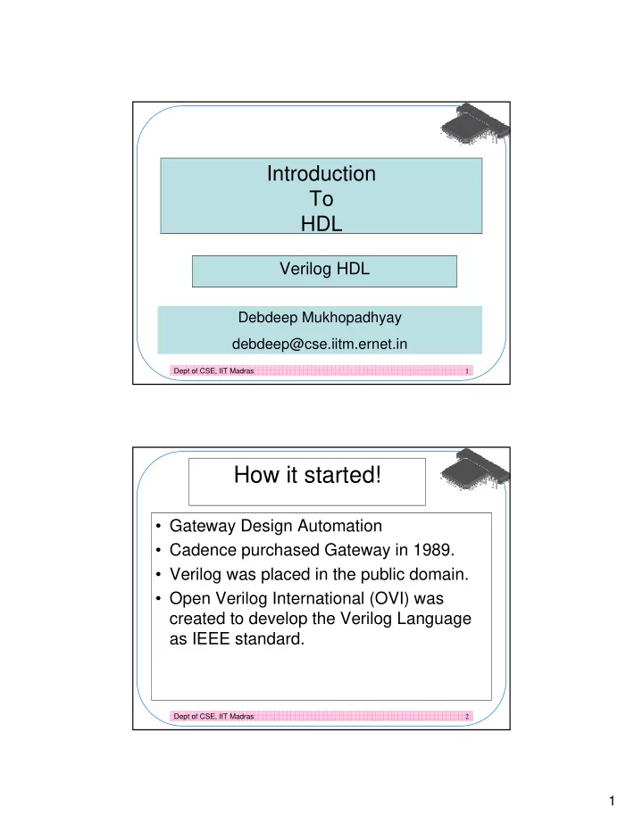
Introduction To HDL
Verilog HDL
Debdeep Mukhopadhyay debdeep@cse.iitm.ernet.in
Dept of CSE, IIT Madras 2
How it started!
- Gateway Design Automation
- Cadence purchased Gateway in 1989.
- Verilog was placed in the public domain.
- Open Verilog International (OVI) was