
SLIDE 1
Hall Effect Measurement System Hall and Hall and van der Pauw - - PDF document
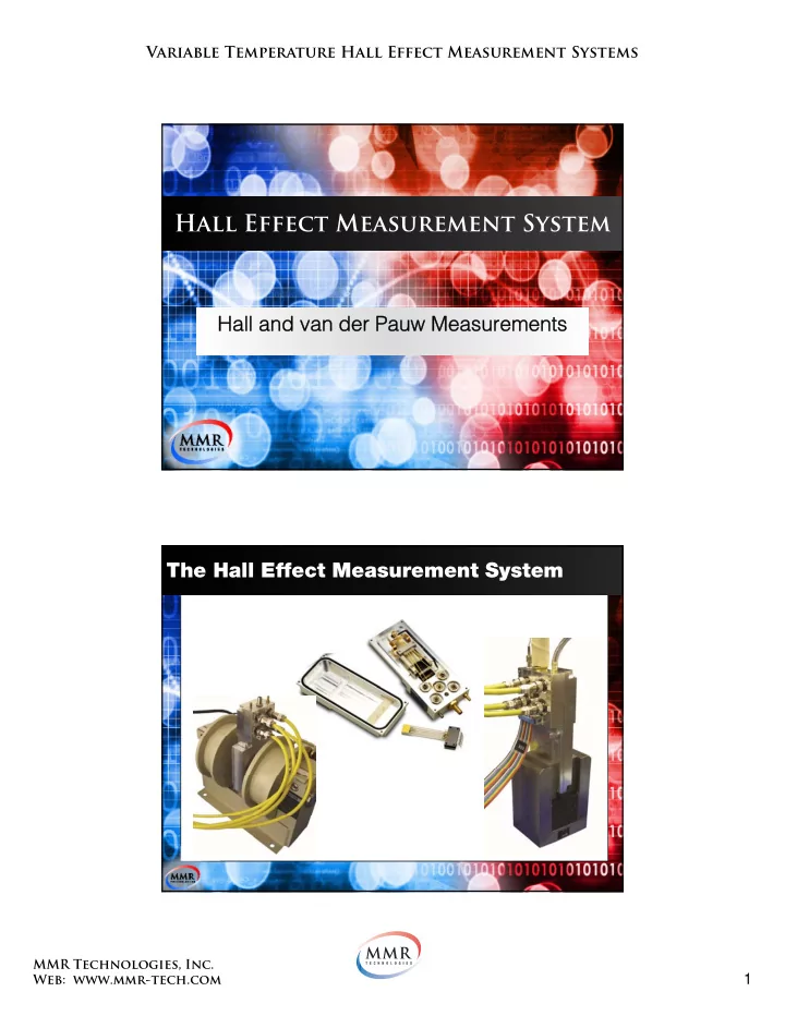
Variable Temperature Hall Effect Measurement Systems Hall Effect Measurement System Hall and Hall and van der Pauw Measurements van der Pauw Measurements The Hall Effect Measurement System MMR Technologies, Inc. 1 Web: www.mmr-tech.com
,
s BD AC s AB,CD
s H