
SLIDE 1
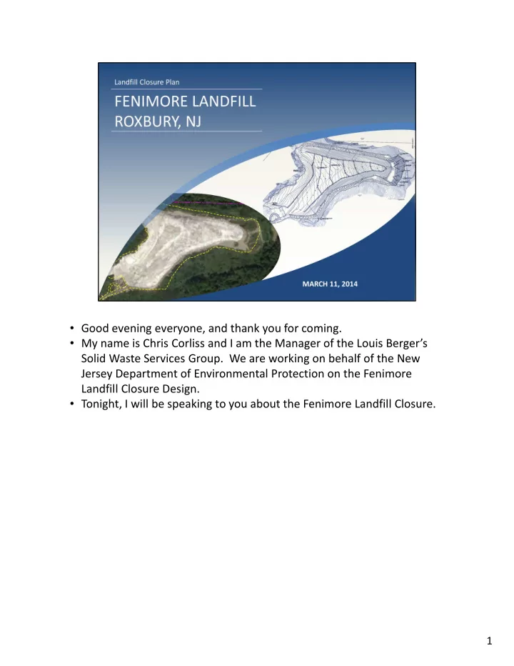
- Good evening everyone, and thank you for coming.
- My name is Chris Corliss and I am the Manager of the Louis Berger’s
Solid Waste Services Group. We are working on behalf of the New Jersey Department of Environmental Protection on the Fenimore Landfill Closure Design.
- Tonight, I will be speaking to you about the Fenimore Landfill Closure.