
SLIDE 1
4: Network Layer 4a-1
10: Inter and intra AS, RIP, OSPF, BGP, Router Architecture
Last Modified: 3/24/2003 2:39:16 PM
4: Network Layer 4a-2
Goals of Routing Protocols
❒ Find the “optimal route” ❒ Rapid Convergence ❒ Robustness ❒ Configurable to respond to changes in many
variables (changes in bandwidth, delay, queue size, policy, etc.)
❒ Ease of configuration
4: Network Layer 4a-3
Real Internet Routing?
❒ CIDR? ❒ Dynamic routing protocols running between
every router?
4: Network Layer 4a-4
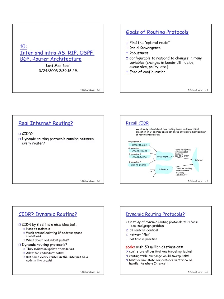
Recall CIDR
“Send me anything with addresses beginning 200.23.16.0/20”
200.23.16.0/23 200.23.18.0/23 200.23.30.0/23
Fly-By-Night-ISP Organization 0 Organization 7 Internet Organization 1 ISPs-R-Us “Send me anything with addresses beginning 199.31.0.0/16”
200.23.20.0/23
Organization 2
. . . . . .
We already talked about how routing based on hierarchical allocation of IP address space can allows efficient advertisement
- f routing information:
4: Network Layer 4a-5
CIDR? Dynamic Routing?
❒ CIDR by itself is a nice idea but..
❍ Hard to maintain ❍ Work around existing IP address space
allocations
❍ What about redundant paths?
❒ Dynamic routing protocols?
❍ They maintain/update themselves ❍ Allow for redundant paths ❍ But could every router in the Internet be a
node in the graph?
4: Network Layer 4a-6