
SLIDE 1
Date: Prepared by: Prepared for:
13290 Evening Creek Drive South, Suite 250 San Diego, CA 92128 T 858.480.2000 F 858.792.8932 www.ata-e.com
Kurt Knutson ATA Engineering, Inc. NSRP 2015 San Diego December 3, 2015
Getting Useful Ship Design 13290 Evening Creek Drive South, Suite - - PowerPoint PPT Presentation
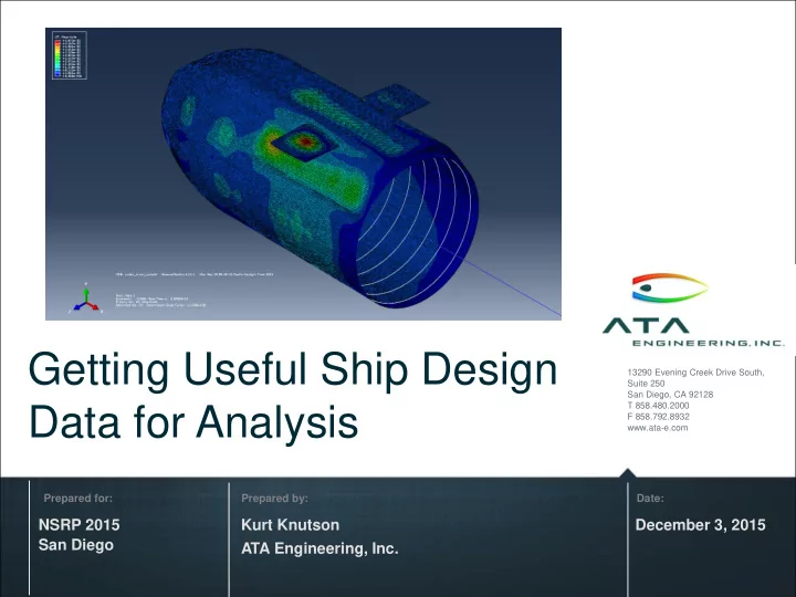
Getting Useful Ship Design 13290 Evening Creek Drive South, Suite 250 San Diego, CA 92128 T 858.480.2000 Data for Analysis F 858.792.8932 www.ata-e.com Prepared for: Prepared by: Date: NSRP 2015 Kurt Knutson December 3, 2015 San Diego
Date: Prepared by: Prepared for:
13290 Evening Creek Drive South, Suite 250 San Diego, CA 92128 T 858.480.2000 F 858.792.8932 www.ata-e.com
Kurt Knutson ATA Engineering, Inc. NSRP 2015 San Diego December 3, 2015
2
3
4
NAVSEA MARCORSYSCOM SSP NAVAIR
N091-052: Automated Transition Of Product Model Data For Ship Design N141-082: Toolset For Nonlinear Prediction Of Woven Ceramic Matrix Composite Material Performance
Image Credit : US Navy 140602-N-ZZ999-202
N142-088: High Efficiency Insulating Barrier for Expeditionary Shelters N108-025: Strain Sensor Calibration
Image Credit : US Navy 150725-N-IP531-086
5
Technology Explanation
kinematic response of a complex mechanism (submarine hatch)
accomplished through a series of increasingly complex mechanism tests
fast-running surrogates for FEA
Contract Details Product Benefits & Applications
engineers to evaluate a multitude of postevent mechanical scenarios for hull, equipment, machinery, and platform damage
contact regions enable more control of mesh fidelity for each region
to enable more efficient simulations Topic No. N141-032 Phase II (2016-17) ATA PI
Contract No. N00024-14- P-4521 Agency Navy Directorate NAVSEA TPOC Randall Goodnight (NSWCCD)
Image credit: US Navy 090109-N-1255R-098
6
Phase II / Option 2 PoP Ended 2/13/2013
– Flexible framework for mapping data among multiple design systems – Expandable methods for data extraction from source, insertion into target
and capabilities :
– Read additional data from ShipConstructor – Write piping and structure data to ShipConstructor
7
8
9
Source: Improved Methods for the Generation of Full-Ship Simulation Models, NSRPComplex_Foundation.stp
10
Gaps Between Parts Overlapping Surfaces Or Bodies Design data translated from STEP Does not have useful beam centerlines or midsurfaces – lots of abstraction needed. What are the weld details? Connection points? Can be challenging to automate
11
Femap command: Geometry, Midsurfaces, Automatic Midsurfaces CAD as imported
12
13
14
Use the “CG of Surface” method to generate beam centerlines quick
consolidate the lines Future automation: Loop over all parts to attempt to identify beam cross sections and extract centerlines
15
(ATA renderings
/Releasable)
ShipConstructor Planar Group Model Type ShipPDX-Assigned ESWBS Number Arbitrary 000 - GENERAL GUIDANCE Curved 111 - SHELL PLATING Deck 130 - HULL DECKS Frame 117 - TRANSVERSE FRAMING LngBhd 121 - LONGITUDINAL STRUCTURAL BLKHDS
16
Can get volume geometry from STEP data but not body or part identifiers or attributes to relate to design data
17
Source: Abaqus model, http://www.isetools.org/eb-cgi-bin/yabb2_ISE/YaBB.pl?num=1380626708 Simulation_Models.zip
18
undex_driver_xpl.inp
properties are missing from input files – appear to have been in “include” files whose type (.bsp) was not included in project archive
available (shown) – how can we use them?
19
20
Select Entire Mesh
21
22
23
24
25
26
27
28
Visit us at www.ata-e.com to see how we can help you meet your services needs. Visit us at www.ata-plmsoftware.com to see how we can help you meet your software needs. And connect with us on LinkedIn.
UNCLASSIFIED UNCLASSIFIED Distribution A: Unlimited 29
Automating the Transition of Product Model Data
CONCEPT DESCRIPTION/REQUIREMENT
Requirement/CAPABILITY GAP: Navy needs access to ship design data to allow analysis of conceptual and preliminary design and for logistical support of as-built designs. To date Navy has had limited success getting as-designed ship configuration into LEAPS. Current methods are manual, extremely time consuming and error prone. DELIVERABLE: Specification of required data entity support (to/from LEAPS); prototype translator software “ShipPDX™”; validated test database; business plan for implementation, support, and maintenance. OBJECTIVE: Near term: develop methods and tools to enable delivery of ship product model data to the Navy. Long term: enable sharing of product model data among shipyards and with Navy during all phases of ship’s life cycle. TRANSITION(S): Following successful demonstration of prototype ShipPDX software, transition to licensed software and implementation of business plan for support, maintenance and customized implementation services.
CONTACTS FUNDING SUMMARY ($K)
Tech Sponsor: NSWC – CD (Elizabeth Madden) Tech Transition POR/Path: DON must specify TPOC: Mr. Ben Kassel TPOC email: Ben.Kassel@navy.mil TWH: none Contractor: ATA Engineering, Inc. Contractor POC: Mr. Gregory W. Antal Contractor email: greg.antal@ata-e.com
SBIR Topic Number: N091-052 Phase II Opt 2 PoP Ended: 2/13/2013
FY 09 FY 10 FY 11 FY 12 FY 13 FY 14 Phase I / Opt 70 30 Phase II 300 Phase II Opt 1 300 Phase II Opt 2 150 CPP TBD Phase III TBD TOTAL 70 30 300 300 150
PLM Systems, Ship Design Tools, Databases, Text Files ShipPDX™ software: Ship Product Data Exchange Modular Architecture. Incrementally create/read LEAPS database.
Related Project