GE Critical Power Overhead Distributed Power Busway for the - - PowerPoint PPT Presentation

ge critical power
SMART_READER_LITE
LIVE PREVIEW

GE Critical Power Overhead Distributed Power Busway for the - - PowerPoint PPT Presentation

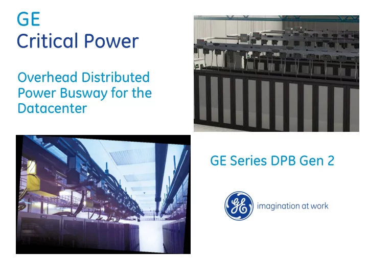
GE Critical Power Overhead Distributed Power Busway for the Datacenter GE Series DPB Gen 2 Series DPB Distributed Power Busway ELECTRICAL SPECS Bus Ratings (Amps): 160/225/250, 400, 800 Voltage: 120 thru 600VAC, 3ph 3w or 4w,


slide-1
SLIDE 1

GE Critical Power

Overhead Distributed Power Busway for the Datacenter GE Series DPB Gen 2

slide-2
SLIDE 2

Series DPB

Distributed Power Busway

ELECTRICAL SPECS

  • Bus Ratings (Amps):

160/225/250, 400, 800

  • Voltage:

120 thru 600VAC, 3ph

  • 3w or 4w, 100% Neutral
  • Frequency:

60 or 50 Hz

  • Short Circuit Capacity:

22KAIC @ 600VAC 35KAIC @ 480VAC 42KAIC @ 208VAC

  • Copper bus bars
  • Class H (220) insulation

2

FEATURES

  • 20-30% less expensive than traditional cable/conduit installs
  • Finger-safe, indoor rated bus system
  • Multiple Rail lengths: 3, 5, 6, 10, 12 feet
  • 99% Recyclable
  • UL/ETL/CE/IEC approved & certified
  • Interchangeable Tap-Off Boxes, 160-400 Amp
  • End Feed/Bus Rail Monitoring, BCM Basic or Plus (optional)
  • Near-wall mounting okay, due to straight-up Tap-Box install
  • Flexible configuration via use of Elbows, Tees, & Cross units
  • Options: 150% Neutral ; 100% Rated Isol Ground
slide-3
SLIDE 3

End Feed (monitoring optional)

Standard or IEC (monitoring – opt) Monitored with whips Standard or IEC w/ whips

Custom Load Distribution (Tap-Off Boxes) Bus Rail Sections

Series DPB

Bus System Main Components

Local Display Monitor (optional)

slide-4
SLIDE 4

The Zenith Series DPB Bus System Busway assembly is comprised of three major elements

Anodized Aluminum Housing

  • protects the assembly
  • improves thermal properties,
  • Incorporates TOUGHRAIL technology allowing
  • ptimized support methods, site specific

labeling and system communication links Bus Bars

  • vary in cross-sectional area depending on

ampacity

  • nickel-plated to resist corrosion and minimize

contact resistance

  • 99% pure electrical grade copper.

Insulators

  • Class B 148° C material
  • enhanced short circuit capability
  • insulating capacity of up to 1000 volts

Series DPB

Bus Rail Technology

slide-5
SLIDE 5

Housing – common housing, 160 - 800 Amps Top channel - bus rail hanger / mounting and grounding plate Side channel – integrated custom labeling, side mount support Integrated communication channel monitor all loads / devices True IP2X-rated bus rail channel opening finger safe! Isolated ground channel (optional) integrated channel design Datacenter A/B Exterior Color Coding standard is black ; red & blue option

Series DPB

Bus Rail Technology

Robust, Configurable, Multi-Purpose Housing Assembly

slide-6
SLIDE 6
  • Improved Bus Rail Coupler is 50% less size,

and doubled the number of contact points. Minimizes resistance and voltage drop.

  • Tested for 60degr C ambient (200-400A)
  • Compact design minimizes “Keep Out Area”,

so more TapOff Boxes can be installed on the rails

  • No special tools required for installation
  • Supports BCMS communication cable for

secure use of installation & maintenance

Series DPB

Bus Rail Coupler Technology

3.75” Industry Leading Keep Out Area

slide-7
SLIDE 7

Two Step Process insures Safety and Electrical Integrity

STEP 1: Mechanical Connection

  • All grounding connections engage &

seat directly to the open bus channel.

  • Top Mast connects mechanically to

the bus rails. Set screws then insure alignment to rails. Rail design prevents backwards installation.

STEP 2: Electrical Connection

  • Once Top Mast is mechanically

secured, the cam action lever seats all electrical contacts against the phase bussing. Once energized, it locks down into position. At this point, the circuit breakers can be safely energized.

Series DPB

Tap-Off Box Connection to Bus Rail

slide-8
SLIDE 8

Series DPB

Tap-Off Boxes

TAP-OFF BOXES

  • 160-400 Amp
  • GE Branch Circuit Breakers, 10 or 22 KAIC
  • Multiple Branch Cord Lengths available
  • Multiple single & duplex receptacles/connectors

available

  • IEC/CE version receptacles & connectors available
  • Branch Circuit Monitoring (optional)

8

slide-9
SLIDE 9

BCMS-equipped Tap-Off Box

End Feed Box Bus Rail

Tap -Off Box Tap Off Box

Communication Cable IntelliBUS Board Communication Connection

MODBUS BMS & DCIM

Local Display Hub

Branch Circuit Monitoring Source Monitoring

Series DPB

Rail & Tap-Off Box Monitoring

Communication Options

slide-10
SLIDE 10

Series DPB

10

Optional Local Display to show Voltage, Current, Current Demand, Crest factor, KVA, KW, PF, kWh, kVAR, % Load

Communications

slide-11
SLIDE 11

Series DPB Busway

GE Website Customer Resources

11

Available Documents

  • DPB Gen 2 Brochure
  • Template Guide Specifications
  • Drawings
  • O&M Manuals
  • Whitepapers
  • And much more…….

www.gecriticalpower.com