
SLIDE 1
IAN WHITE ASSOCIATES
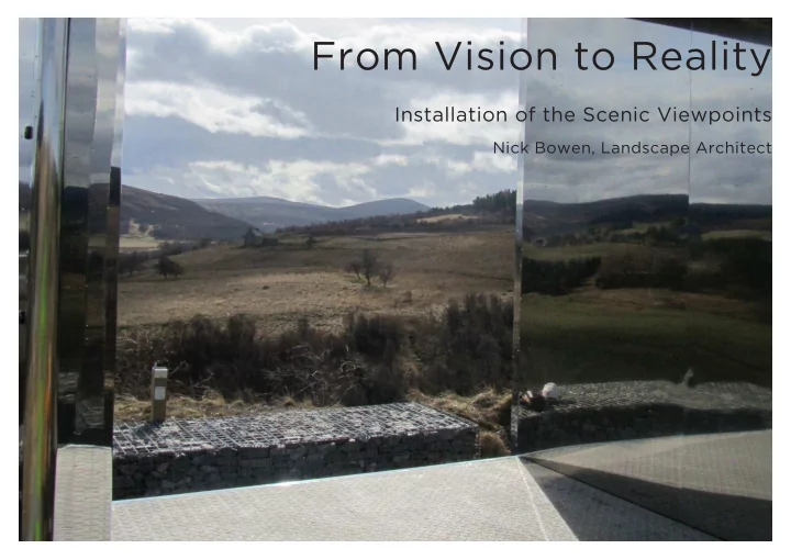
From Vision to Reality
Installation of the Scenic Viewpoints
Nick Bowen, Landscape Architect
From Vision to Reality Installation of the Scenic Viewpoints Nick - - PowerPoint PPT Presentation
IAN WHITE ASSOCIATES From Vision to Reality Installation of the Scenic Viewpoints Nick Bowen, Landscape Architect IAN WHITE ASSOCIATES Our Role We are Landscape Architects; we design and manage the implementation of works in the external
IAN WHITE ASSOCIATES
Nick Bowen, Landscape Architect
IAN WHITE ASSOCIATES
We are Landscape Architects; we design and manage the implementation
Reserves to university quadrangles and urban redevelopment. Our role on this project :
To manage the design and delivery of the 3 Scottish Scenic Viewpoints in the Cairngorms National Park
IAN WHITE ASSOCIATES
Our Key objectives :
Scottish Scenic Routes Project Phase 3
C:\Users\David.Aitken\Desktop\DavidsAitken Old Laptop DJA\Documents\CSIC\scottish canals\SSR Ph3 Pilot Project Delivery issue 4.mpp 1 , TOMINTOUL UPGRADING EXTENSION Drawing 1996/TOM/01 specifically refers 128 m2 £ - B 13 m3 £ - C 17 m3 £ - D Compact formation for new layby construction 128 m2 £ - E Type 1 sub-base; 200 thick; consolidated 128 m2 £ - F Crushed stone dust blinding; 25 thick 128 m2 £ - VIEWPOINT PATH UPGRADING Drawing 1196/TOM/01 specifically refers G 108 m2 £ - H Type 1 sub-base; 100 thick; compacted to camber 108 m2 £ - WOODLAND PLANTING PREPARATION I 125 m2 £ - J 100 m3 £ - To Collection £ - Carefully cut turf to a minimum depth of 150; set aside in low stacks Excavate over area not exceeding 0.25 deep to remove organic topsoil layer; stockpile in adjacent work areas on grass or tarpaulin sheets Excavate below through consolidated quarry waste and stockpile Scrape crushed stone surface of existing track clean IAN WHITE ASSOCIATES
IAN WHITE ASSOCIATES
IAN WHITE ASSOCIATES
IAN WHITE ASSOCIATES
IAN WHITE ASSOCIATES
views
IAN WHITE ASSOCIATES
IAN WHITE ASSOCIATES
IAN WHITE ASSOCIATES
3 separate planning applications, to 3 different authorities - PKC, Moray & Aberdeenshire
IAN WHITE ASSOCIATES
Bringing the design through to a point where it could be built
Designers
03
SCALE 1:10 UNWRAPPED ELEVATION OF PROPOSED SEATING01
SCALE 1:20 DETAIL OF TIMBER SEATING SUPPORT04
SCALE 1:5 NOTE Refer to Specification for concrete works on drawing 1996/DE/06. PLAN VIEW02
SCALE 1:50 Re-located boulder; positioned as agreed with Landscape Architect on site. Typically 250mm depth Existing car park surface. New footpath (detail 06) Swale SWALE DETAIL05
SCALE 1:20 25mm depth crushed stone fines; laid and rolled damp. 300 250 100 150 200mm depth Type 1 sub-base. Precast concrete kerb Porous geotextile membrane; Terram 1000. Concrete foundation and haunch. 1/40 NEW FOOTPATH DETAIL05
SCALE 1:20 IAN WHITE ASSOCIATES
IAN WHITE ASSOCIATES
Constructed during November 2015. Snowfall interrupted first week of groundworks, but then the weather held fine for the installation. Unfortunately, extreme wet weather then intervened, causing damage to paths and reinstatements. Transplanted turves and heath soil have been used, to provide for restoration of heath ground flora. This will take a little time.
IAN WHITE ASSOCIATES
Constructed during August 2016. Light rain + no wind + standing about looking at kerbs = Midgeageddon Precast elements and modular design = Good finish quality Grass seeding failed to establish before heavy winter rains. Were reseeded in May 2017.
“Hello Peter... I didn’t recognise you”
IAN WHITE ASSOCIATES
Layby and gabion constructed during September 2016. Cladding supplier error lead to delay of viewpoint feature installation until March 2017. Quality more important than programme. Fortunately, the steelwork quality proved to be worth the wait. Natural regeneration of the species-rich grassland is ongoing; this includes on the grassed gabions.
IAN WHITE ASSOCIATES
IAN WHITE ASSOCIATES
IAN WHITE ASSOCIATES
IAN WHITE ASSOCIATES
IAN WHITE ASSOCIATES
IAN WHITE ASSOCIATES
IAN WHITE ASSOCIATES
John, Daniel, Phil, Angus and Daniel - The Designers Hunter Construction (Aberdeen) Ltd - Main Contractor Chris Brammall Ltd - Specialist steelwork manufacturer Plean Precast - Precast concrete manufacturer Our Client, Peter Crane of CNPA and of course the landowners: Invercauld Estate Allargue Estate Glenlivet Estate (Crown)
IAN WHITE ASSOCIATES