
SLIDE 1
Flow through and around groups of bodies
Andre Nicolle & Ian Eames
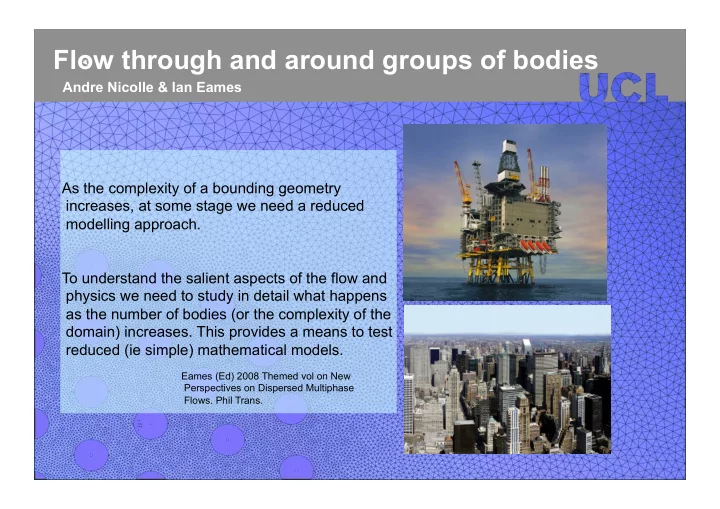
t = 34 s t = 6 s Door vortexAs the complexity of a bounding geometry increases, at some stage we need a reduced modelling approach. To understand the salient aspects of the flow and physics we need to study in detail what happens as the number of bodies (or the complexity of the domain) increases. This provides a means to test reduced (ie simple) mathematical models.
Eames (Ed) 2008 Themed vol on New Perspectives on Dispersed Multiphase
- Flows. Phil Trans.