FINTE ELEMENT ANALYSIS OF THE MECHANICAL PROPERTIES OF WOVEN - - PDF document

finte element analysis of the mechanical properties of
SMART_READER_LITE
LIVE PREVIEW

FINTE ELEMENT ANALYSIS OF THE MECHANICAL PROPERTIES OF WOVEN - - PDF document

18 TH INTERNATIONAL CONFERENCE ON COMPOSITE MATERIALS FINTE ELEMENT ANALYSIS OF THE MECHANICAL PROPERTIES OF WOVEN COMPOSITE JiangGuang Zhai 1 , YiQi Wang 1 , Jong-Rae Cho 2 , JungII Song 1 * 1 Department of Mechanical Engineering, Changwon


slide-1
SLIDE 1

18TH INTERNATIONAL CONFERENCE ON COMPOSITE MATERIALS

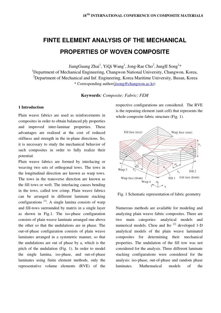
1 Introduction Plain weave fabrics are used as reinforcements in composites in order to obtain balanced ply properties and improved inter-laminar properties. These advantages are realized at the cost of reduced stiffness and strength in the in-plane directions. So, it is necessary to study the mechanical behavior of such composites in order to fully realize their potential. Plain weave fabrics are formed by interlacing or weaving two sets of orthogonal tows. The tows in the longitudinal direction are known as warp tows. The tows in the transverse direction are known as the fill tows or weft. The interlacing causes bending in the tows, called tow crimp. Plain weave fabrics can be arranged in different laminate stacking configurations [1]. A single lamina consists of warp and fill-tows surrounded by matrix in a single layer as shown in Fig.1. The iso-phase configuration consists of plain weave laminate arranged one above the other so that the undulations are in phase. The

  • ut-of-phase configuration consists of plain weave

laminates arranged in a symmetric manner, so that the undulations are out of phase by a, which is the pitch of the undulation (Fig. 1). In order to model the single lamina, iso-phase, and out-of-phase laminates using finite element methods, only the representative volume elements (RVE) of the respective configurations are considered. The RVE is the repeating element (unit cell) that represents the whole composite fabric structure (Fig. 1).

  • Fig. 1 Schematic representation of fabric geometry

Numerous methods are available for modeling and analyzing plain weave fabric composites. There are two main categories: analytical models and numerical models. Chou and Ito [2] developed 1-D analytical models of the plain weave laminated composites for determining their mechanical

  • properties. The undulation of the fill tow was not

considered for the analysis. Three different laminate stacking configurations were considered for the analysis: iso-phase, out-of-phase and random phase laminates. Mathematical models

  • f

the

FINTE ELEMENT ANALYSIS OF THE MECHANICAL PROPERTIES OF WOVEN COMPOSITE

JiangGuang Zhai1, YiQi Wang1, Jong-Rae Cho2, JungII Song1*

1Department of Mechanical Engineering, Changwon National University, Changwon, Korea,

2Department of Mechanical and Inf. Engineering, Korea Maritime University, Busan, Korea

* Corresponding author(jisong@changwon.ac.kr)

Keywords: Composite; Fabric; FEM

slide-2
SLIDE 2

c p e u s a T s I p la th m c la w d in to T c d T fi w m s a th 2 2 T g fr th (R th w configuration predictions o experiments undulation o inusoidal an assumed for The iso-strain tiffness of th shikawa and predict the

  • aminates. Th

he stiffness model negle composite as

  • aminates. Th

was used to depending on n series or

  • w crimp, th

The fiber un considers fi direction but The bridging fiber undulat weave fabric model [3] for tiffness pred a straight edg he analysis p 2 Geometric 2.1 Finite Ele The geomet geometry of t from measur he faces of RVE). From he bounds o warp cross-se ns were ex

  • f inplane m

for all th

  • f warp to

nd two typ the fill tow n condition w he plain weav d Chou [3,4] elastic pro he mosaic m

  • f satin wea

cts the tow an assembla hen, an iso-s predict the n whether th

  • parallel. Sin

he prediction ndulation m iber undula neglects it model [4], a tion model,

  • cs. The mo

r plain wea diction is not ge model wa process. modeling ement Mode tric model the RVE of a rements take f the repre m photomicro

  • f the tow in

ection were xplained ve modulus are hree config

  • w was as

pes of cros s: sinusoidal was used for ve laminates developed th

  • perties of

model [3] was ave fabric c w crimp and age of asymm tress or iso-s e stiffness o he laminates nce the mod n of stiffness

  • del [3] or t

ation in th in the transv combination was devel

  • del reduces

ave fabrics t accurate. In as designed t eling describing a single lami en on photom sentative vo

  • graphs of t

n the fill cro almost symm ery well a e compared

  • gurations. T

ssumed to ss-section w l and elliptic r evaluating . hree models woven fab used to pred

  • mposites. T

d idealizes metric cross- strain condit

  • f the lamin

are assemb del neglects is not accura the 1-D mo he longitudi verse directi n of mosaic a

  • ped for sa

s to the cri and hence n this studyi trying to sim g the inter na is develop micrographs

  • lume elem

the RVE fac

  • ss-section a

metry in pla and to The be were cal. the s to bric dict The the

  • ply

tion nate bled the ate.

  • del

inal ion. and atin imp the ing, mply rnal ped s of ment ces, and ane. Th sur dep tow rem dir as pro fol Fro cur we lin the sim Th ele 4.

  • ri

Th

to mi is he RVE c rrounded by picting the t ws in the maining two rection (fill t a unidirec

  • perties in

llows the tow

  • Fig. 2 Photo
  • m the pho

rvature of th e could subst ne, which wi e model of mulation resu

  • Fig. 3 3-

he models w ement of SOL The materia ientation of t he fiber volum calculate icromechanic very diffic

  • nsists of

y the matrix.

  • tows. Two o

x-direction

  • represent

tows). Each ctional com the materia w undulation

  • micrograph

tomicrograp he bounds o titute the cur ill greatly si the unit cel ult as well.

  • D views of a

were meshe LID-95 in A l properties o the path line. me fraction e the to

  • cs. Although

cult to mea four inter . There are

  • f them repre

n (warp tow two half to volume (tow mposite with l coordinate n.

  • f the fill fa

h of the RV f the tow is rve boundary implify the c l, and retain a plain weav ed using 20 ANSYS [5], as

  • f the tows v

. in the tow V

  • w

prope h the tow vo asure directl rtwined tow four volume esent two ha ws) and th

  • ws in the y

w) is modele h orthotrop e system th ce of fabric VE faces, th so small th y for a straigh complexity o n precision o ve fabric 0 node soli s shown in F vary along th Vf is necessar erties usin

  • lume fractio

y, it can b ws es alf he y- ed ic hat he hat ht

  • f
  • f

id ig. he ry ng

  • n

be

slide-3
SLIDE 3

FINTE ELEMENT ANLYSIS OF THE MECHANICAL PROPERTIES OF WOVEN COMPOSITE

calculated from the overall volume fraction Vo and the calculated mesoscale volume fraction Vg. It was easily to calculate the fiber volume fraction in this model, which is 0.5.

  • Fig. 4 Finite element model of the weave fabric

2.2 Material Properties and Calculation of Elasticity Modulus The material properties of the tows are calculated using micromechanics [6, 7] with V 0f as fiber volume

  • fraction. The elastic properties of constituent

materials (fiber and matrix) for the CERL fabric are

  • btained from [8] and for the remaining materials

from [2]. The tows are transversely isotropic and thus require only five properties (E1, E2, G12, m12, m23). Then, the properties are assigned to the tow and matrix elements in ANSYSTM. The next step is to apply the boundary conditions and analyze the

  • results. Since AS4 carbon fiber is transversely

isotropic, the elastic properties are calculated using periodic microstructure micromechanics for transversely isotropic fibers [7]. As an alternative [6] to while taking into account transversely isotropic fibers with a simple model

[9], the following

procedure is proposed. First, calculate E1 using the warp fiber modulus Ef1 and m12f of the fiber, and the elastic properties of matrix. Next, calculate E2 using the radial fiber modulus Ef2 and m12f of the fiber, and elastic properties of matrix. Then, calculate G12 using the value of G12f, m12f of the fiber and elastic properties of matrix. Finally, calculate G23 using Ef2, m23f of the fiber and elastic properties of matrix, where m23f is calculated from the transversely isotropic conditions. These properties are checked for the restrictions on elastic constants [8]. The results are compared with [6] that assumes fibers to be transversely isotropic and with [6], that uses only longitudinal fiber properties Ef1 and m12f. The results obtained from the approximate procedure show good correlation with the micromechanics model for transversely isotropic

  • fibers. The elastic properties of the constituent

materials and the overall properties of the tow (composite) are reported in Table 1. Table 1 Elastic properties of the fiber and matrix of RVE Fiber Matrix El longit.[GPa] 221 Em [GPa] 3.4 Et transv.[GPa] 16.6 v 0.35 v 0.26

  • Fig. 5 Tensile deformation of finite element model

As shown in Fig.5, the Elasticity modulus in x- direction could be calculated by the loading a nonzero displacement on the face which is located at X=lw . According to the periodic boundary condition, symmetrical boundary conditions were loaded on the faces which are located at X=0, Y=0 and Z=0. The nodes should be coupled together on faces which are located at Y=Hz and Z=lz so that the deformation will be in the same pattern in the faces. The total reaction forces in x-direction on face located at X=lw

slide-4
SLIDE 4

could be obtained in the analysis result [10]. The elasticity modulus in x-direction could be calculated by the following equation-1.

x H l l F E

z z w x x

Δ × × × = ∑

The elasticity modulus in the other two directions could be calculated using the same method introduced previously. 3 Analysis Results The elasticity modulus in x-direction and y-direction has been calculated in this studying respectively. The analysis results using FEM are listed in the following figures. Fig. 6 shows the deformation in x- direction, from which we can see that, the deformation is continuously distributed on every elements.

  • Fig. 6 Displacement nephogram of the whole model
  • Fig. 7 shows the stress in x-direction, from which we

can see that, the fabric bundles mainly endured the tensile stress. This is because elasticity modulus of fabric bundle is higher than the matrix material. The calculated elasticity modulus in x-direction is 10 GPa, and in y-direction is 1.25Gpa, which are higher than matrix (3.4GPa) and lower than fabric (221Gpa and 16.6GPa).

  • Fig. 7 Stress nephgram of the whole model

4 Conclusions In this studying, the elasticity properties of plain weave fabrics using FEM. The geometric model was based on microphotograph measurements which were translated into a solid model and an FE model using commercial software. The elasticity values predicted by the FEM were thought to be reasonable for the weave fabrics. We want to prove the analysis results with experiment in the following research. References

[1] E.J. Barbero, J.Trovillion, J.A.Mayugo, K.K. Sikkil “Finite element modeling of plain weave fabrics from photomicrograph measurements”. Composite Structures, Vol. 73, pp41-52, 2006. [2] Chou TW, Ito M. “An analytical and experimental study of strength and failure behavior of plain weave composites”. Journal of Compos Mater, Vol.3, pp.22–30, 1998. [3] Ishikawa T, Chou TW. “One-dimensional micromechanics analysis

  • f

woven fabric composites”. J Am Instit Aeronaut Astronaut, Vol.21, pp.1714–1721, 1983. [4] Ishikawa T, Chou TW. “Stiffness and strength behavior of wovenfabric composites”. Journal of

slide-5
SLIDE 5

FINTE ELEMENT ANLYSIS OF THE MECHANICAL PROPERTIES OF WOVEN COMPOSITE Material Science, Vol.17, pp.3211–3220, 1982. [5] ANSYS 5.6 User Manual, ANSYS Inc. Southpointe, 275 Technology Drive, Canonsburg, PA15317, USA. [6] Barbero EJ, Luciano R. “Formulas for the stiffness of composites with periodic microstructure”. International Journal of Solid Structure, Vol.31, pp. 2933–2943. 1994. [7] Barbero EJ, Luciano R. “Micromechanics formulas for the relaxation tensor of linear viscoelastic composites with transversely isotropic fibers ” . International Journal of Solid Structure, Vol.32, pp.1859–1872, 1995. [8] Barbero EJ. “Introduction to composite materials design”. Philadelphia, PA: Taylor and Francis; 1999. [9] Barbero EJ, Damiani TM, Trovillion J. “Micromechanics of fabric reinforced composites with periodic microstructure”. International Journal

  • f Solid Structure, Vol.42, pp.2489–2504, 2005.

[10] W.F. Dong, J.Xiao, Y.Li “Finite element analysis of the mechanical properties

  • f

2.5D braided composites”. Journal of Materials Science & Engineefing, Vol. 25, No. 5, pp 657-666, 2007.