Feasibility of Cathodic Plasma Electrolytic Oxidation for Corrosion - - PDF document

feasibility of cathodic plasma electrolytic oxidation for
SMART_READER_LITE
LIVE PREVIEW

Feasibility of Cathodic Plasma Electrolytic Oxidation for Corrosion - - PDF document

Transactions of the Korean Nuclear Society Virtual Spring Meeting July 9-10, 2020 Feasibility of Cathodic Plasma Electrolytic Oxidation for Corrosion Resistant Stainless Steel against Chloride-based Matter Jaewoo Lee a , Sangyoon Lee a , Jun Heo


slide-1
SLIDE 1

Feasibility of Cathodic Plasma Electrolytic Oxidation for Corrosion Resistant Stainless Steel against Chloride-based Matter

Jaewoo Leea, Sangyoon Leea, Jun Heoa, and Sung Oh Choa

  • aDept. of Nuclear and Quantum Engineering, Korea Advanced Institute of Science and Technology (KAIST),

291, Daehak-ro, Yuseong-gu, Daejeon, Republic of Korea, 34141

*Corresponding author: socho@kaist.ac.kr

  • 1. Introduction

Due to the saturation of the use of wet storage sites, several studies are underway to switch to the dry storage

  • system. Austenitic stainless steels are mainly used as a

material for dry storage canisters, however, which are very vulnerable to chloride-induced stress corrosion cracking (CISCC). Since most nuclear power plants use seawater as a coolant, it is likely to be exposed to the salt environment as it is located on the seaside. In order to utilize dry storage, it is worth noting that austenitic stainless steels should be prevented from CISCC. Various methods have been developed to enhance the durability of metals. Among them, plasma electrolytic

  • xidation (PEO) has been arising as a simple method for

fabricating a protective oxide layer on the metal surface. In PEO, it is possible to fabricate a robust and compact

  • xide layer than other types of oxide layers using local

plasma heat. The oxide layer inhibits the penetration of corrosive substances into the base material. However, it has been reported that stainless steel is unsuitable for applying PEO [1]. For metals with limited PEO processing, cathodic plasma electrolytic oxidation (CPEO) is emerging as a new alternative, switching an anode part and cathode part each other [2,3]. Therefore, CPEO uses target metal as the cathode and less reactive metal as the anode. CPEO process has some advantages; simple and efficient process, no need to pretreatment, eco-friendliness, and preparing robust and dense (i.e., high mechanical properties) oxide layer. Nevertheless, there are no any studies use CPEO to increase the corrosion resistance of stainless steel. In this study, a prospective CPEO method to prepare a protective oxide layer on austenitic stainless steel surface. Additionally, a plausible mechanism about the formation

  • f the oxide layer is also presented. The prepared oxide

layer may play an important role in preventing corrosion. Furthermore, we also evaluate the corrosion behavior of cathodic plasma electrolytic oxidized (CPEO-ed) stainless steel in the chloride environment.

  • 2. Materials and Methods

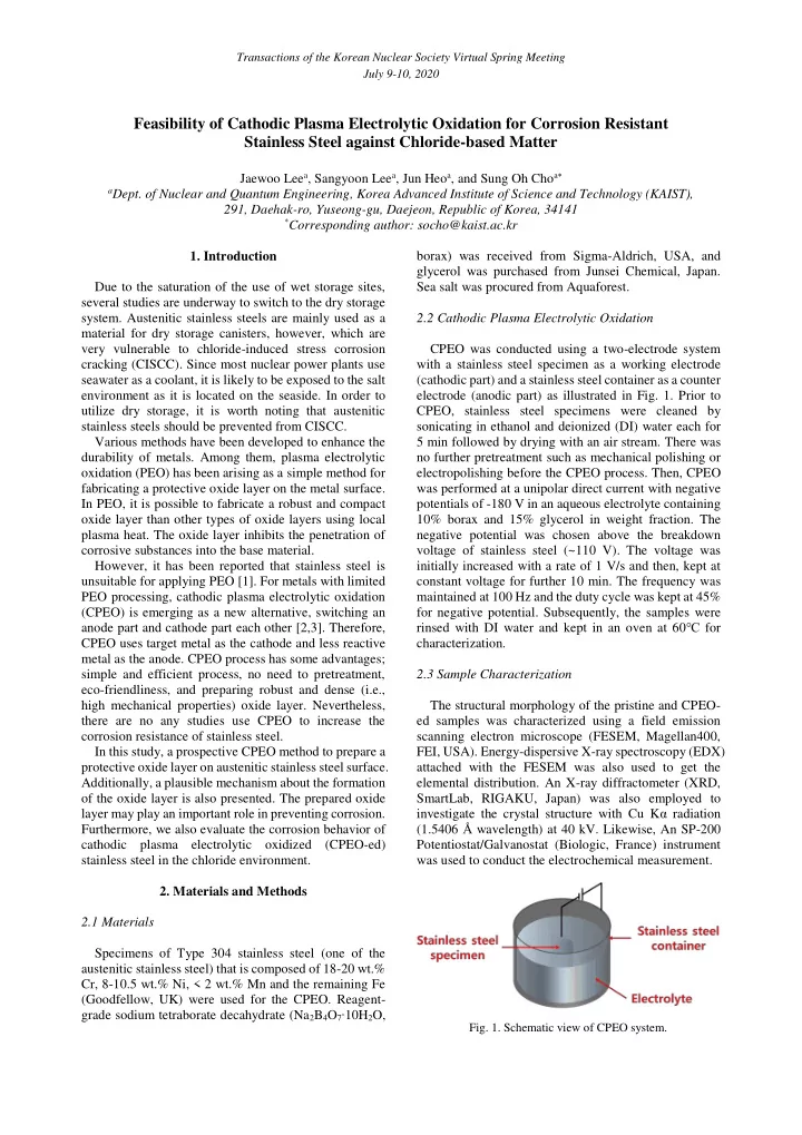
2.1 Materials Specimens of Type 304 stainless steel (one of the austenitic stainless steel) that is composed of 18-20 wt.% Cr, 8-10.5 wt.% Ni, < 2 wt.% Mn and the remaining Fe (Goodfellow, UK) were used for the CPEO. Reagent- grade sodium tetraborate decahydrate (Na2B4O7∙10H2O, borax) was received from Sigma-Aldrich, USA, and glycerol was purchased from Junsei Chemical, Japan. Sea salt was procured from Aquaforest. 2.2 Cathodic Plasma Electrolytic Oxidation CPEO was conducted using a two-electrode system with a stainless steel specimen as a working electrode (cathodic part) and a stainless steel container as a counter electrode (anodic part) as illustrated in Fig. 1. Prior to CPEO, stainless steel specimens were cleaned by sonicating in ethanol and deionized (DI) water each for 5 min followed by drying with an air stream. There was no further pretreatment such as mechanical polishing or electropolishing before the CPEO process. Then, CPEO was performed at a unipolar direct current with negative potentials of -180 V in an aqueous electrolyte containing 10% borax and 15% glycerol in weight fraction. The negative potential was chosen above the breakdown voltage of stainless steel (~110 V). The voltage was initially increased with a rate of 1 V/s and then, kept at constant voltage for further 10 min. The frequency was maintained at 100 Hz and the duty cycle was kept at 45% for negative potential. Subsequently, the samples were rinsed with DI water and kept in an oven at 60℃ for characterization. 2.3 Sample Characterization The structural morphology of the pristine and CPEO- ed samples was characterized using a field emission scanning electron microscope (FESEM, Magellan400, FEI, USA). Energy-dispersive X-ray spectroscopy (EDX) attached with the FESEM was also used to get the elemental distribution. An X-ray diffractometer (XRD, SmartLab, RIGAKU, Japan) was also employed to investigate the crystal structure with Cu Kα radiation (1.5406 Å wavelength) at 40 kV. Likewise, An SP-200 Potentiostat/Galvanostat (Biologic, France) instrument was used to conduct the electrochemical measurement.

  • Fig. 1. Schematic view of CPEO system.

Transactions of the Korean Nuclear Society Virtual Spring Meeting July 9-10, 2020

slide-2
SLIDE 2

2.4 Potentiodynamic Polarization The corrosion property was investigated by the electrochemical method, potentiodynamic polarization. The polarization technique was conducted using a conventional three-electrode cell system consisting of stainless steel samples as a working electrode with an exposed surface area of 1 cm2, graphite as a counter electrode, and a saturated calomel electrode as a reference electrode. Prior to the potentiodynamic polarization measurement, all samples were mechanically polished with SiC polishing papers and washed subsequently with ethanol and DI water. The measurement was conducted by polarizing the samples in a potential range from -250 to 250 mV. Artificial seawater was employed as the electrolyte for mimicking chloride-based matter. The chemical composition of the artificial seawater is given in Table I. Such efforts can

  • btain the polarization curve and determine corrosion-

related parameters such as the corrosion current density (icorr) and the corrosion potential (Ecorr). The icorr was determined by the extrapolation of the cathodic and anodic Tafel plots to the Ecorr. The corrosion rate (CR) was calculated by the following expression,

𝐷𝑆 =

𝑗𝑑𝑝𝑠𝑠𝑁 𝑜𝑒𝐵 × 3270 (1)

where M is the molecular mass of steel, in the unit of g, n is the number of valance electron, d is the density of steel, in g/cm3, and A is the exposed sample area (1 cm2). In Eq. 1, icorr is in the unit of A/cm2 and consequently, the unit of CR becomes mm/yr. Here, the constant 3,270 is employed for conversion factor.

Table I: Chemical composition of the artificial seawater.

Element Cl Na Mg S Composition (g/L) 19.00 9.72 1.30 0.81 Element Ca K Sr B Composition (g/L) 0.40 0.35 0.007 0.004

  • 3. Results and Discussion

3.1 Structural Morphology Following the CPEO treatment of stainless steel, the surface condition was somewhat changed. Fig. 2 demonstrates the morphology of the CPEO-ed stainless

  • steel. In order to compare the surface morphology of

CPEO-ed sample with that of pristine stainless steel, the stainless steel was electropolished using ethylene glycol monobutylether containing 5 vol.% perchloric acid with constant 60 V at -5℃ for 30 min. Fig. 2b shows that the surface has some non-uniform tiny pores after CPEO

  • treatment. The pores are the region where plasma

discharges have occurred. In addition, there are some cracks, suggesting molten oxides are solidified repeatedly due to plasma heat and cooling. Meanwhile, the elemental distribution of the CPEO-ed surface was investigated. Oxygen distribution can be identified as shown in Fig. 2c. Furthermore, the prepared layer consists mainly of Fe and O supporting that the iron

  • xide layer may be formed on the surface of stainless

steel (Fig. 2d). This suggests Fe was most dominantly reacted with oxygen species among the metallic components of stainless steel. The atomic proportion of Fe and O is approximately 3:4, which supports the Fe3O4 layer may be synthesized on the stainless steel surface. Additionally, two distinguishable layers are seen and the thickness of the layers is approximately 21.3 µm for the outer layer and 22.9 µm for inner one as given in Fig.

  • 3. The elemental distribution of each layer is quite
  • different. Interestingly, the outer layer has a higher ratio
  • f Fe elements than the inner layer. This demonstrates Fe

movement is faster among the elements of stainless steel, Fe, Cr, and Ni, and reacts first with oxygen. The Cr

  • Fig. 2. Surface FESEM images of (a) pristine stainless steel and

(b) CPEO-ed stainless steel, EDX (c) mappings and (d) spectrum of CPEO-ed stainless steel. Transactions of the Korean Nuclear Society Virtual Spring Meeting July 9-10, 2020

slide-3
SLIDE 3

content, on the other hand, is found to be significantly higher in the inner layer. This also supports Fe has been

  • xidized preferentially than Cr.

The crystal structure of the oxide layer on the stainless steel surface was also characterized. Fig. 4 indicates the two layers formed on the stainless steel surface consist

  • f different materials. In the outermost layer, some clear

peaks of around 30.04°, 35.52°, and 62.73° match well with Fe3O4 (magnetite, ICDD PDF No. 01-084-9337). This result has something in common with the EDX

  • results. There is another structure, γ-(Fe, Ni) (taenite,

ICDD PDF No. 00-047-1417), whose peaks fit well at 43.54° and 50.65°. However, the fraction of taenite is very low since the Ni content in Fig. 2d is only ~2.71 at.%. It strongly suggests the outer layer of CPEO-ed stainless steel has a magnetite layer. The formation of the crystalline magnetite is the result of the oxidation at a very high temperature. Likewise, the inner layer consists mainly of Fe0.64Ni0.36 (ICDD PDF No. 00-047-1405), which has a cubic crystalline structure. The prominent peaks can be found at 43.56°, 50.79°, and 74.59°. Fe0.64Ni0.36 is known to be synthesized by reducing NiFe2O4 [4] and the spinel phase of NiFe2O4 has high

  • hardness. Therefore, the formation of Fe0.64Ni0.36 is

beneficial to enhance corrosion resistance from CISCC.

  • Fig. 3. Cross-sectional (a) FESEM image and (b) EDX spectra
  • f CPEO-ed stainless steel.
  • Fig. 4. XRD spectra of the (a) pristine stainless steel, (b) inner

layer, and (c) outermost layer of CPEO-ed stainless steel.

3.2 Corrosion Analysis The potentiodynamic polarization curves of pristine and CPEO-ed sample, are given in Fig. 5. It can be seen that Ecorr of CPEO-ed specimen is closer to zero in a more positive direction. It suggests surface-treated stainless steel by CPEO has a lower potential for corrosion. Table Ⅱ presents the potentiodynamic parameters derived from the polarization curves. The parameters were calculated using Tafel extrapolation. icorr of CPEO-ed stainless steel (6.57×10⁻⁷ A/cm2) has a lower value than that of pristine stainless steel (1.074×10⁻⁶ A/cm2). CRs calculated from

  • Eq. 1 are 1.158×10⁻² mm/yr for the pristine sample and

7.084×10⁻³ mm/yr for the CPEO-ed sample. Likewise, corrosion resistance efficiency (η%P) is simply calculated by Eq. 2,

𝜃%𝑄 =

𝑗𝑑𝑝𝑠𝑠

𝑞

−𝑗𝑑𝑝𝑠𝑠

𝑑

𝑗𝑑𝑝𝑠𝑠

𝑞

× 100 (2)

where 𝑗𝑑𝑝𝑠𝑠

𝑞

is the corrosion current density of pristine stainless steel and 𝑗𝑑𝑝𝑠𝑠

𝑑

is the corrosion current density

  • f CPEO-ed stainless steel. The corrosion resistance

efficiency of CPEO-ed stainless steel is ~38.8% and the pre-oxidized layer demonstrates increased corrosion

  • resistance. It seems the densely formed CPEO-ed layers

protect stainless steel by preventing the penetration of corrosive materials such as Cl.

  • Fig. 5. Potentiodynamic polarization curves of pristine and

CPEO-ed stainless steel. Table Ⅱ: Potentiodynamic polarization parameters and CR.

System Ecorr (mV/SCE) icorr (A/cm2) CR (mm/yr) Pristine stainless steel

  • 194.5

1.074×10⁻⁶ 1.158×10⁻² CPEO-ed stainless steel

  • 125.5

6.57×10⁻⁷ 7.084×10⁻³

Transactions of the Korean Nuclear Society Virtual Spring Meeting July 9-10, 2020

slide-4
SLIDE 4
  • Fig. 6. Schematic diagram depicting the formation mechanism of the protective oxide layer via CPEO.

3.3 Mechanism of Oxide Layer Formation We have found that a protective oxide layer was formed on a stainless steel surface when a high voltage was applied between two electrodes. So far, there has been no fully established theory of the CPEO mechanism. Here, a plausible approach to the mechanism in which the oxide layer is fabricated on a stainless steel surface by CPEO is described. CPEO is generally explained as plasma discharge, which is very relevant to the breakdown. As illustrated in

  • Fig. 6, (I) before the breakdown voltage, the current

density increases as voltage increases such as a typical

  • conductor. A gaseous envelope grows, which is almost

composed of hydrogen gas and vapor. (Ⅱ) When the applied voltage reaches the breakdown voltage, the discharge occurs. It causes the components in the electrolyte to disintegrate into their elements, creating highly reactive radicals. Such radicals are mainly hydrogen, carbon, and oxygen due to water and glycerol in the electrolyte, followed by the formation of a plasma discharge envelope. (Ⅲ) Subsequently, the combination

  • f Fe atoms on the stainless steel surface and oxygen

radicals in plasma discharge envelope prevails and (Ⅳ) forms an oxide layer. This reaction takes place locally in the whole region of the surface. Since the temperature is approximately 1,000~10,000 K [5], the oxide layer formed previously is molten. In the interphase between cathodic parts, the molten oxide is cooled down and

  • solidified. Due to the repetition of melting and

solidifying the oxide layer becomes very dense. The

  • xide layer is crystalline and has considerably high
  • hardness. This is consistent with the results derived from

the XRD analysis. However, vast researches on the exact mechanism remain further works.

  • 4. Conclusions

This study has proposed a promising method to prepare a protective pre-oxidized layer on a typical type 304 stainless steel surface using CPEO treatment. When the high negative voltage above the breakdown is applied to stainless steel, the plasma discharge occurs. These local plasma discharges create a plasma discharge envelope and initiate high-temperature oxidation due to reactive oxygen radicals in the envelope. Consequently, Fe and O combine to form an oxide layer on the stainless steel surface. The fabricated oxide layer has some pores and cracks but two nonidentical layers are formed. The thickness is ~21.3 µm for the outermost layer and is almost the same for the inner layer. The component of the outermost

  • xide layer is mainly crystalline Fe3O4 and it may be very

robust because of formation at high temperature. The inner layer is made of Fe-Ni alloy (i.e., Fe0.64Ni0.36) and is very compact and hard. In addition, stainless steel with a CPEO-ed surface exhibits extraordinary corrosion resistance in artificial seawater medium. In the potentiodynamic polarization, stainless steel treated by CPEO shows a corrosion rate of approximately 7.084×10⁻³ mm/yr and has a corrosion resistance efficiency of ~38.8% compared with pristine stainless steel. However, the theory of the CPEO mechanism has not been fully established yet, so plenty

  • f further works are necessary. As a result, the CPEO

method used in this study can be applied to prevent CISCC by increasing corrosion resistance from chloride- based matters in austenitic stainless steel. REFERENCES

[1] T. W. Clyne and S. C. Troughton, A review of recent work

  • n discharge characteristics during plasma electrolytic
  • xidation of various metals, International Materials Reviews,

Vol.64(3), pp.127-162, 2019. [2] S. Stojadinović, N. Tadić, N. M. Šišović, and R. Vasilić, Real-time imaging, spectroscopy, and structural investigation

  • f cathodic plasma electrolytic oxidation of molybdenum,

Journal of Applied Physics, Vol.117, 233304, 2015. [3] J. Yu, Y. Zhang, X. Jin, L. Chen, J. Du, and W. Xue, Fabrication and optical emission spectroscopy of enhanced corrosion-resistant CPEO films on Q235 low carbon steel, Surface & Coatings Technology, Vol.363, pp.411-418, 2019. [4] K. S. Abdel-Halim, M. Bahgat, and O. A. Fouad, Thermal synthesis of nanocrystalline fcc Fe-Ni alloy by gaseous reduction of coprecipitated NiFe2O4 from secondary resources, Journal of Materials Science and Technology, Vol.22(12), pp.1396-1400, 2006. [5] X. Jin, L. Chen, J. Yu, R. Liu, W. Xue, and H. Shang, Temperature measurement and OES analysis during CPEO on stainless steel, Surface & Coatings Technology, Vol.363, pp.314-321, 2019. Transactions of the Korean Nuclear Society Virtual Spring Meeting July 9-10, 2020