FASTENER AS FAIL-SAFE DISBOND/DELAMINATION ARREST FOR LAMINATED - - PDF document

fastener as fail safe disbond delamination arrest for
SMART_READER_LITE
LIVE PREVIEW

FASTENER AS FAIL-SAFE DISBOND/DELAMINATION ARREST FOR LAMINATED - - PDF document

18 TH INTERNATIONAL CONFERENCE ON COMPOSITE MATERIALS FASTENER AS FAIL-SAFE DISBOND/DELAMINATION ARREST FOR LAMINATED COMPOSITE STRUCTURES C. H. Cheung 1 , P. Gray 1 , K. Y. Lin 1 1 Department of Aeronautics and Astronautics, University of


slide-1
SLIDE 1

18TH INTERNATIONAL CONFERENCE ON COMPOSITE MATERIALS

1 Introduction The goal of this research is to develop a comprehensive understanding and analysis package for applying fasteners as a fail-safe mechanism for disbond/delamination arrest in laminated composite structure in aerospace applications. A properly sized mechanical fastener, whose primary purpose is to fasten different parts together during assembly, is

  • ne way to provide damage tolerance to disbond/

delamination (here referred to as crack) type

  • damages. Such design has the potential to increase

structural efficiency, enhance safety, and can be used as basis for certification. A plane-strain FEA model for understanding the effectiveness of fastener as crack arrest mechanism has been constructed. The elastic behavior of the fastener is modeled using linear springs using fastener flexibility approach by Huth [2]. The FEA results show that the fastener provides significant crack retardation capability in both Mode I and Mode II loading conditions. An analytical model based on the principle of minimum potential energy (PMPE) is developed. The model consists of a split-beam with a fastener

  • attached. An interference-triggered elastic layer is

placed between the beams on the cracked faces to resolve contacts. The mode-decomposed strain energy release rates (SERR) are solved analytically using Qiao’s crack tip element (CTE) [7-9]. The ultimate goal is to develop a computationally efficient analysis tool to predict crack arrest effectiveness for optimization and probabilistic

  • analysis. Multiple failure modes may be considered

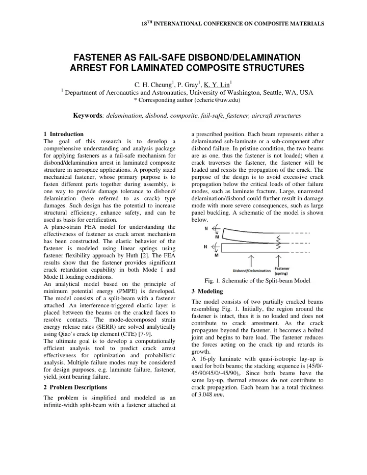
for design purposes, e.g. laminate failure, fastener, yield, joint bearing failure. 2 Problem Descriptions The problem is simplified and modeled as an infinite-width split-beam with a fastener attached at a prescribed position. Each beam represents either a delaminated sub-laminate or a sub-component after disbond failure. In pristine condition, the two beams are as one, thus the fastener is not loaded; when a crack traverses the fastener, the fastener will be loaded and resists the propagation of the crack. The purpose of the design is to avoid excessive crack propagation below the critical loads of other failure modes, such as laminate fracture. Large, unarrested delamination/disbond could further result in damage mode with more severe consequences, such as large panel buckling. A schematic of the model is shown below.

  • Fig. 1. Schematic of the Split-beam Model

3 Modeling The model consists of two partially cracked beams resembling Fig. 1. Initially, the region around the fastener is intact, thus it is no loaded and does not contribute to crack arrestment. As the crack propagates beyond the fastener, it becomes a bolted joint and begins to bare load. The fastener reduces the forces acting on the crack tip and retards its growth. A 16-ply laminate with quasi-isotropic lay-up is used for both beams; the stacking sequence is (45/0/- 45/90/45/0/-45/90)s. Since both beams have the same lay-up, thermal stresses do not contribute to crack propagation. Each beam has a total thickness

  • f 3.048 mm.

FASTENER AS FAIL-SAFE DISBOND/DELAMINATION ARREST FOR LAMINATED COMPOSITE STRUCTURES

  • C. H. Cheung1, P. Gray1, K. Y. Lin1

1 Department of Aeronautics and Astronautics, University of Washington, Seattle, WA, USA

* Corresponding author (ccheric@uw.edu)

Keywords: delamination, disbond, composite, fail-safe, fastener, aircraft structures

slide-2
SLIDE 2

AS4/3501-6 laminar material properties are used. Ply thickness = 0.1905 mm; E1 = 127.5 GPa; E2 = E3 = 11.3 GPa; G12 = G13 = 6.0 GPa; G23 = 3.6 GPa; ν12 = ν13 = 0.3; ν23 = 0.4; GIC = 0.2627 N/mm; GIIC = 1.226 N/mm; mixed-mode fracture parameter used in the B-K law is η = 1.75, shown in Eq. (1).  

II equiv IC IIC IC I II

G G G G G G G

         

(1) The fastener is made of Titanium, with E = 114

  • GPa. The fastener interacts with the two beams via

the fastener flexibility model [2], shown in Eq. (2). For single-lap bolted graphite/epoxy joints, the constants are a = 2/3, b = 4.2 and n = 1. The resulting joint stiffness is 1/C.

1 2 1 1 2 2 1 3 2 3

1 1 1 1 2 2 2

a

t t b C d n t E nt E t E nt E                 

(2) It is assumed that disbond/delamination in laminated composites propagates in a self-similar fashion. Thus, the crack tip always remains at the prescribed interface between the two beams regardless of load conditions. 3.1 FEM Model in Abaqus The fastened split-beam is modeled in Abaqus using a combination of a plane-strain elements and spring elements that which describes the equivalent elastic behavior of the fastener joint. Strain energy release rate used to calculate crack propagation is evaluated using Virtual Crack Closure Technique (VCCT). Crack face friction, fastener preload, thermal stresses can be optional included. Each ply is represented by one element, thus each element has a thickness of 0.1905 mm. Element length is 1.5 times the thickness, which provides converged VCCT and displacement results. Initially, the intact region is modeled by tying the nodes of the two beams at the interface with displacement constraints. The FEA solver iterates for a load magnitude that yields exactly the SERRs needed to propagate the crack. Then, the tie constraint at the node at the crack tip is released,

  • pening the crack. The next node along the interface

becomes the new crack tip. 3.2 Analytical Model The analytical model includes two separate beams attached to a fixed boundary, which represents the crack tip. The crack tip does not need to be modeled elastically since the CTE already considers crack tip rotation and shear deformation. A set of springs attached to the free end of the beams represent the

  • fastener. Loads are applied to the free end of the

beams, assuming that the far field loads reaches the fastener location unaltered. A layer of “infinite stiffness” contact springs is placed between the beams. The contact springs are

  • nly activated when interference is detected;

interference must be resolved iteratively. The stiffness of the contact springs is selected such that convergence can be obtained without generating numerical errors related to machine size numbers. System equilibrium is solved using PMPE. Trigonometric series are used as shape functions for the beams. The energy contribution by the contact spring is shown in Eq. (3), where w1 and w2 are the shape functions of the split beams. Force and moment equilibrium provides input for determining the SERRs using Qiao’s CTE.

 

2 2 1 1

1 | 2

N EL n n L n N

U k w w

      

 

(3) Although contact is resolved iteratively, each step is a linear elastic analysis, thus retaining the computational efficiency of the method. Competing failure modes, such as surface strain failure, fastener failure and joint failure, can easily be integrated into this method to provide a comprehensive design tool. 4 Results and Discussions 4.1 FEM Results Fig.2 shows a load vs. crack length curve for a load case with an opening moment applied to only one of the beams. This asymmetric load case yields mixed- mode, though primarily Mode I, SERR components at the crack tip. The fastener is located at crack location zero. The horizontal portions of the curves imply that the crack propagation is unstable, which is catastrophic in nature. The case without the fastener shows that the crack propagation is totally unstable with no

  • pportunity of arrest.

In the case with a fastener, when the crack propagates pass fastener, it is slowed by the arresting effect of the fastener, as shown by the rising load

  • curve. The load required to propagate the crack just

2 mm beyond the fastener is double the initial

slide-3
SLIDE 3

3 FASTENER AS FAIL-SAFE DISBOND/DELAMINATION ARREST FOR LAMINATED COMPOSITE STRUCTURES

propagation load before the crack reaches the

  • fastener. The crack propagation is stable; stability is

depicted by the slope of the curve, i.e. higher slope is more stable. This stability is the most affected by the size and material of the fastener, and to a lesser degree by the laminate lay-up and laminar material properties. 5 10 15 20 25

  • 1

1 2 Applied Moment (N-m)

Crack Length vs. Applied Moment

Without Fastene With Fastener

  • Fig. 2. Applied Moment vs. Crack Length

Fig.3 shows the SERR components vs. crack length, which details the mechanisms with which the fastener arrests the crack. Each point on the curves represents a propagation event, the crack length, GI and GII are recorded for the event. The load, which is not shown in Fig.3, is the load at which crack propagation occurs, and can be referred to in Fig.2. The absolute SERR values are plotted, meaning that GI peaks at 0.2627 N/mm and GII peaks at 1.226 N/mm. Before the crack reaches the fastener, the propagation is mixed mode, but dominated by Mode

  • I. As the crack passes the fastener, GI decreases. In
  • rder for the crack to continue to propagate, GII has

to increase to make up for the loss in GI, such that the total equivalent G in Eq. (1) is maintained. The absolute change in magnitude of GII is higher than that of GI is because GIIC is much higher than GIC. The change from mixed mode to pure Mode II propagation corresponds to the increase in propagation load shown in Fig.2. The fastener provides crack arrestment capability via two primary mechanisms. The first is the straight- forward elastic constraints provided by the fastener. In Mode I, the fastener restricts the opening between the two beams. This mode is exceptionally effective because the axial stiffness of the fastener is very high compared to any

  • ut-of-plane

loads experienced by the beams. In Mode II, the fastener resists the relative sliding between the two beams by providing a bolted-joint. This mode is less effective because the joint stiffness, given by Eq. (2), is much lower than the laminate properties; also, the applied in-plane loads in a laminate structure can be very high. 0.2 0.4 0.6 0.8 1 1.2 1.4

  • 1

1 2 SERR Components (N/mm) SERR Components vs. Crack Length

GI - With Fastener GI - Without Fastener GII - With Fastener GII - Without Fastener

  • Fig. 3. SERR Components vs. Crack Length

The second mechanism is the less obvious ability for the fastener to change the fracture mode of the crack, as illustrated by Fig.3. Since the fastener has a high axial stiffness, Mode I is shut down almost

  • immediately. In the event that the load case is pure

Mode I, the crack would be completely stopped as soon as it reaches the fastener. In the general case with mixed-mode loading, in order for the crack to continue to propagate, GII has to increase to make up for the loss in GI. However, in a mixed-mode load case, the component of load that typically generates GI is absorbed by the fastener, leaving only the component that generates GII to do the entire work. Also, GIIC is generally much higher than GIC; by restricting the crack to only propagate in pure Mode II, the strength of the material has effectively

  • increased. Thus, the magnitude of load required to

propagate the crack drastically increases. In the event that the load case is pure Mode II, the benefit

  • f the fastener is not as high.
slide-4
SLIDE 4

4.2 Analytical Results The analytical method is compared with the FEA results in this section. The load case used is pure Mode I for simplicity, with equal and opposite transverse shear loads applied to the two beams. Multiple fastener sizes are analyzed. All of the curves have a vertical asymptot, indicating a completely arrested crack for all fastener sizes. 50 100 150 200 250 2 4 Load (N) Crack Length (mm) Opening Load vs. Crack Length

FEM (d = 6.35mm) Analytical (d = 6.35mm) FEM (d = 3.175mm) Analytical (d = 3.175) FEM (d = 1 5875mm)

  • Fig. 4. Opening Load vs. Crack Length

The FEA and analytical results show varying levels

  • f discrepencies, especially at large fastener sizes. In

general, the analytical method exhibits a higher degree of sensitivity towards fastener size. However, both approaches consistently predicts the arresting behavior of the fastener. The cause of the discrepencies could be the fact that the beam model used in the analytical method is rigid in the thickness direction. In the FEM model, the beams can deform elastically when loaded in the thickness direction, i.e. by the fastener. This has a softening effect

  • n

the FEM model. This discrepency becomes higher when the fastener becomes stiffer and causes more deformation in the thickness direction. 5 Conclusion Analysis of effectiveness of fastener as crack arrest feature in composite structure has been

  • demonstrated. In the split-beam FEA model, it is

shown that the presence of the fastener is highly effective in arresting the propagation of a crack. The fastener arrests the crack via two primary mechanisms: 1) its elastic influence on the structure, and 2) its ability to restrict crack propagation to pure Mode II. It is shown that the fastener effectively eliminates GI by restricting the

  • pening

displacement behind of the crack tip, forcing the crack to propagate in pure Mode II. The benefit is the highest for load conditions normally resulting in the most Mode I SERR component at the crack tip. The load required for crack propagation drastically increases, achieving the desired effect of crack

  • arrestment. In general, the presence of a fastener-like

crack arrest mechanism will turn normally catastrophic unstable crack propagation into a stable

  • ne, providing fail-safety to the structure.

An analytical model is developed with the use of an analytical CTE solution to determine the mode- decomposed SERRs. The solution is obtained using principle of minimum potential energy. The analytical method predicts similar behaviors as the

  • FEA. However, some levels of discrepancies are
  • bserved. The error could be due to the fact that the

FE model can deform in the thickness direction, thus softening the effect of the fastener. Other failure modes, including laminate failure, fastener yield, fastener pull through and joint bearing failure, are not considered in this study. A proper design of such crack arrest mechanism should take into account all other failure modes. The goal of the current research is to provide airframe designers with a method to analyze the effectiveness of fastener-like crack arrest features. The outcomes of this research will contribute to the design and certification of efficient composite

  • structures. The understanding of crack arrest

mechanism may provide an alternative method for repairing damaged structures in operation. Future work will focus on the development of the analytical method and the design of verification experiments. Acknowledgments This work was jointly supported by the FAA Center

  • f Excellence at the University of Washington

(AMTAS) and The Boeing Company. The authors wish to express their sincere thanks to Marc Piehl, Gerald Mabson and Eric Cregger of Boeing for their technical advice and guidance.

slide-5
SLIDE 5

5 FASTENER AS FAIL-SAFE DISBOND/DELAMINATION ARREST FOR LAMINATED COMPOSITE STRUCTURES

References

[1] G. Mabson and L. Deobald “Design Curves for 3D Reinforced Composite Laminated Double Cantilever Beams,” Proc of ASME Int. Mechanical Eng. Congress and Expo., 2000. p. 89–99. [2] H. Huth “Influence of Fastener Flexibility on the Prediction of Load Transfer and Fatigue Life for Multiple-Row Joints,” Fatigue in Mechanically Fastened Composite and Metallic Joints, ASTM STP 927, John M. Potter, Ed., American Society for Testing and Materials, Philadelphia, 1986, pp. 221- 250 [3] About.com, “Carbon/Graphite Composite Materials,” http://composite.about.com/cs/data/l/blcarbon.htm [cited 20th Feb, 2009] [4] J. Reeder, S. Kyongchan, P. Chunchu, and D. Ambur “Postbuckling and Growth of Delaminations in Composite Plates Subjected to Axial Compression” 43rd AIAA/ASME/ASCE/AHS/ASC Structures, Structural Dynamics, and Materials Conference, Denver, Colorado, vol. 1746, p. 10, 2002. [5] G. Mabson, L. Deobald and B. Dopker “Fracture Interface Elements for the Implementation of the Virtual Crack Closure Technique,” AIAA-2007-2376, 48th AIAA/ASME/ASCE/AHS/ASC Structures, Structural Dynamics, and Materials Conference, Honolulu, Hawaii, Apr. 23-26, 2007. [6] A. Freudenthal, P. Wang "Ultimate strength analysis

  • f aircraft structures" Journal of Aircraft, 1970,

0021-8669 vol.7 no.3 (205-210). [7] J. Wang and P. Qiao “On the Energy Release Rate and Mode Mix of Delaminated Shear Deformable Composite Plates,” International Journal of Solids and Structures 41, 2757-2779, 2004. [8] P. Qiao and J. Wang “Novel Joint Deformation Models and Their Application to Delamination Fracture Analysis,” Composites Science and Technology 65, 1826-1839, 2005. [9] J. Wang and P. Qiao “Fracture Analysis of Shear Deformable Bi-Material Interface,” Journal of Engineering Mechanics, pp. 306-316, March 2006. [10]

  • P. Gray, C. Cheung and K. Lin “Design Tool for

Laminated Composite Structures Disbond Arrest Mechanism,” SAMPE 2010 Spring Conference and Exhibition, Seattle, WA, May 17-20, 2010.