SLIDE 1
GSI Helmholtzzentrum für Schwerionenforschung GmbH 19.06.2019 PANDA Stefan Koch 1
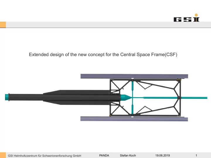
Extended design of the new concept for the Central Space Frame(CSF)
SLIDE 2
GSI Helmholtzzentrum für Schwerionenforschung GmbH 19.06.2019 PANDA Stefan Koch 2
Contents:
1. Requirements 2. Material comparison 3. Overview of the first concept 4. Extended design 5. Conclusion
SLIDE 3 GSI Helmholtzzentrum für Schwerionenforschung GmbH 19.06.2019 PANDA Stefan Koch 3
Requirements:
- CSF has to carry the STT, the MVD and possibly the DCDC and the GBT electronics
Electronic: ~180kg in its center of gravity 1506 mm upstream from the interaction point STT: ~80kg MVD: ~30kg
- CSF has to fix the target pipe and the target cross
- The volume of material has to be preferably low
- The material of the frame should have a low density and a low nuclear charge number
1. Requirements
SLIDE 4
GSI Helmholtzzentrum für Schwerionenforschung GmbH 19.06.2019 PANDA Stefan Koch 4
Regarding to the requirement described, carbon composite seems to be the best choice for the central space frame.
material Titan Aluminum CFRP (carbon composite) density
4,5 g/cm³ 2,7 g/cm³ ~1,6 g/cm³
nuclear charge number
22 13 6*
young‘s modulus
105 GPa 80 GPa ≥ 125 GPa 2. Material comparision
SLIDE 5 GSI Helmholtzzentrum für Schwerionenforschung GmbH 19.06.2019 PANDA Stefan Koch 5
Suggestions:
- 1. An CSF design in combination with an additional support structure for the electronics. It could release the
beam pipe of the critical torque without any further needs for suspensions during transport or mounting.
- 2. With two bellows perpendicular to the target pipe, instead of the current welded flange, critical stresses in the
target cross could be avoided.
3. Overview of the first concept
SLIDE 6
GSI Helmholtzzentrum für Schwerionenforschung GmbH 19.06.2019 PANDA Stefan Koch 6
In the first design the CSF and the support structure was made of two separate symmetric halves, to be connected in the Y,Z-plane of the target cross. The two halves should be attached together with screws at the roller skates of the rails of the Barrel DIRC.
3. Overview of the first concept
CSF left target pipe CSF right
SLIDE 7
GSI Helmholtzzentrum für Schwerionenforschung GmbH 19.06.2019 PANDA Stefan Koch 7
The picture below shows the extended design of the CSF with the CT beams of the Barrel DIRC. The CT beams carries the guiding system for the CSF and the inner detectors. The following slides shows a short overview of the seperatet components of the assembly.
4. Extended design
target pipe CSF CT beam CT beam
SLIDE 8
GSI Helmholtzzentrum für Schwerionenforschung GmbH 19.06.2019 PANDA Stefan Koch 8
The first component of the CSF is the mainframe. It is splitted no longer in two parts, which makes production and mounting more easily. Integrated in the mainframe are several inserts for anchor points of the detectors and the roller and guiding system.
4. Extended design
SLIDE 9
GSI Helmholtzzentrum für Schwerionenforschung GmbH 19.06.2019 PANDA Stefan Koch 9
For the movement rollers with ball-bearings are in charge. Because of the magnetic field and the radiation the rollers and the bearings are made out of technical ceramic.
4. Extended design
mainframe upstream roller downstream rollers
SLIDE 10
GSI Helmholtzzentrum für Schwerionenforschung GmbH 19.06.2019 PANDA Stefan Koch 10
Because of the hole for the target pipe the CSF has to cross, two rollers are needed on the downstream side.
4. Extended design
upstream roller downstream rollers ~50
SLIDE 11
GSI Helmholtzzentrum für Schwerionenforschung GmbH 19.06.2019 PANDA Stefan Koch 11
The single roller on the upstream side has an eccentric bolt for adjusting the CSF in vertical axis. By loosen the lock nut and turning the Bolt, the roller move the CSF up or down.
4. Extended design
locknut Excentric bolt roller e
SLIDE 12
GSI Helmholtzzentrum für Schwerionenforschung GmbH 19.06.2019 PANDA Stefan Koch 12
For an additional guiding only perpendicular of the beam, two components made of PEEK are foreseen.
4. Extended design
mainframe upstream roller downstream rollers horizontal guide horizontal guide
SLIDE 13
GSI Helmholtzzentrum für Schwerionenforschung GmbH 19.06.2019 PANDA Stefan Koch 13
With the rollers and the guides, the main frame can be attached to a mounting beam. The following pictures shows the CT beams of the Barell Dirc instead of a possible mounting beam.
4. Extended design
mainframe upstream roller downstream rollers horizontal guide horizontal guide CT beam CT beam
SLIDE 14
GSI Helmholtzzentrum für Schwerionenforschung GmbH 19.06.2019 PANDA Stefan Koch 14
Attached to the CT beam is a guide shaft made of hard anodized aluminum. The guide shaft is clicked into a aluminum profile from the company ITEM. This Profile is pressed into a groove of the CT beam.
4. Extended design
upstream roller guide shaft click profile CT beam
SLIDE 15
GSI Helmholtzzentrum für Schwerionenforschung GmbH 19.06.2019 PANDA Stefan Koch 15
Attached to the CT beam is a guide shaft made of hard anodized aluminum. The guide shaft is clicked into a aluminum profile from the company ITEM. This Profile is pressed into a groove of the CT beam.
4. Extended design
guide shaft click profile CT beam downstream roller
SLIDE 16
GSI Helmholtzzentrum für Schwerionenforschung GmbH 19.06.2019 PANDA Stefan Koch 16
The second component of the CSF is the support structure for the electronic. The support structure is splitted in two identical parts on the west and the east side. .
4. Extended design
support structure GBT‘s DCDC changer
SLIDE 17
GSI Helmholtzzentrum für Schwerionenforschung GmbH 19.06.2019 PANDA Stefan Koch 17
Together with the target pipe, both support structures will be connected to the mainframe via screws. With the mainframe, the four components build a very stiff assembly. .
4. Extended design
CT beam mainframe support structure support structure CT beam target pipe screws and nuts target pipe front view
SLIDE 18
GSI Helmholtzzentrum für Schwerionenforschung GmbH 19.06.2019 PANDA Stefan Koch 18
The next two components are the two adapter for the bayonet lock at the cross and the adapter for the target pipe at the downstream side. .
4. Extended design
SLIDE 19
GSI Helmholtzzentrum für Schwerionenforschung GmbH 19.06.2019 PANDA Stefan Koch 19
The connection between the target pipe and the CSF is made via wedge shaped half shells. This half shells are made out of PEEK and are located at three points of the CSF. .
4. Extended design
target pipe half shells half shells target pipe target pipe half shells
SLIDE 20
GSI Helmholtzzentrum für Schwerionenforschung GmbH 19.06.2019 PANDA Stefan Koch 20
The principal working of the half shells based on clamping the target pipe against the CSF via a wedge geometry. For realizing that, wedge shaped geometries are integrated in the CSF as well.
4. Extended design
half shell target pipe CSF half shell CSF target pipe wedge shaped geometry in the CSF (here by way for example at he upstream side)
SLIDE 21
GSI Helmholtzzentrum für Schwerionenforschung GmbH 19.06.2019 PANDA Stefan Koch 21
Here again the summary of the individual components of the CSF.
4. Extended design
1x mainframe 3x roller 2x horizontal guides 2x support structure 2x adapter for bayonet 1x adapter downstream 4x half shell upstream 2x half shell downstream
SLIDE 22
GSI Helmholtzzentrum für Schwerionenforschung GmbH 19.06.2019 PANDA Stefan Koch 22
The last two slides shows the CSF at its later position in the target spectrometer with and without the electronic, which will be attached to the support structure.
4. Extended design
SLIDE 23
GSI Helmholtzzentrum für Schwerionenforschung GmbH 19.06.2019 PANDA Stefan Koch 23
The last two slides shows the CSF at its later position in the target spectrometer with and without the electronic, which will be attached to the support structure.
4. Extended design
SLIDE 24
GSI Helmholtzzentrum für Schwerionenforschung GmbH 19.06.2019 PANDA Stefan Koch 24
pros cons
Target pipe will not be loaded by the electronic The diameter of the target pipe has to be reduced from 150 mm to 140 mm(in the area of the support structure ) There is no need for suspensions during the mounting of the detectors The CSF would be more complex regarding to the additional structure No temporary suspension rods are necessary while installation the BW EMC in the spectrometer There is a lower risk to cause damage to the target pipe, while exchange the suspensions for example We need no welded anchor points on the target pipe for suspensions for the electronics By the seperated support structures, assembly of the electronic should be more flexible The mounting of the hole assembly can be done on the final rails system
5. Conclusion