EVALUATION OF CRACK ARRESTER WITH SEMI- CYLINDRICAL SHAPE UNDER MODE - - PDF document

evaluation of crack arrester with semi cylindrical shape
SMART_READER_LITE
LIVE PREVIEW

EVALUATION OF CRACK ARRESTER WITH SEMI- CYLINDRICAL SHAPE UNDER MODE - - PDF document

18 TH INTERNATIONAL CONFERENCE ON COMPOSITE MATERIALS EVALUATION OF CRACK ARRESTER WITH SEMI- CYLINDRICAL SHAPE UNDER MODE II TYPE LOADING Y. Hirose 1 *, H. Matsuda 2, G. Matsubara 2 and M. Hojo 3 1 Department of Aeronautics, Kanazawa Institute of


slide-1
SLIDE 1

18TH INTERNATIONAL CONFERENCE ON COMPOSITE MATERIALS

1 Introduction Recently, composite materials have been widely used in aircraft structures. However, most of them are direct replacements of materials from metals to composites retaining the same structural concept of a semi-monocoque structure. This structural concept is suitable for metal structures such as a sheet metal built-up one. Therefore, it is very difficult to realize the full potential capability of composite materials that are suitable for integral structures [1-2]. Research studies on suitable structural concepts for composite materials are necessary. A foam core sandwich panel structure is one of the suitable structural concepts to realize the full potential capability of composite materials for integral structures [3-9]. However, this structure has a critical problem, namely, no visual indications of impact damages due to a hail attack etc. were found. In our previous research, we estimated the reduction

  • f the static and fatigue strengths quantitatively [10].

Moreover, an interfacial crack between a surface sheet and a foam core, initiated from the damage area, would propagate under the surface sheet without any indication. The suppression of the interfacial crack is necessary in the application of a foam core sandwich panel structure to actual airframe structures. Some researchers have conducted basic studies on crack suppression

  • methods. These methods are unsuitable for airframe

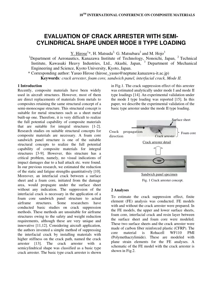
structures owing to the safety and weight reduction requirements, although these are very unique and innovative [11,12]. Considering aircraft application, the authors invented a simple method of suppressing the interfacial crack by installing materials with higher stiffness on the crack path, named the crack arrester [13]. The crack arrester with a semicylindrical shape was classified as a basic type crack arrester. The basic type crack arrester is shown in Fig.1. The crack suppression effect of this arrester was estimated analytically under mode I and mode II type loadings [14]. An experimental validation under the mode I type loading was reported [15]. In this paper, we describe the experimental validation of the basic type arrester under the mode II type loading. 2 Analyses To estimate the crack suppression effect, finite element (FE) analysis was conducted. FE models with and without the crack arrester were prepared. In the FE models, the upper and lower surface sheets, foam core, interfacial crack and resin layer between the surface sheet and foam core were modeled. These two surface sheets and the crack arrester were made of carbon fiber reinforced plastic (CFRP). The core material is Rohacell WF110 PMI (Polymethacrylimide). These are modeled with plane strain elements for the FE analyses. A schematic of the FE model with the crack arrester is shown in Fig.2.

EVALUATION OF CRACK ARRESTER WITH SEMI- CYLINDRICAL SHAPE UNDER MODE II TYPE LOADING

  • Y. Hirose1*, H. Matsuda2, G. Matsubara2 and M. Hojo3

1Department of Aeronautics, Kanazawa Institute of Technology, Nonoichi, Japan, 2 Technical

Institute, Kawasaki Heavy Industries, Ltd., Akashi, Japan, 3 Department of Mechanical Engineering and Science, Kyoto University, Kyoto, Japan. * Corresponding author: Yasuo Hirose (hirose_yasuo@neptune.kanazawa-it.ac.jp) Keywords: crack arrester, foam core, sandwich panel, interfacial crack, Mode II.

  • Fig. 1 Crack arrester concept.

Crack propagation direction Crack arrester Foam core Surface sheet Sandwich panel specimen Crack arrester detail

slide-2
SLIDE 2

The ABAQUS Ver.6.4.1 FEM code was used in this analyses and the total energy release rate was selected to estimate the crack arrester effect

considering the mixed mode condition at the

crack tip.

The energy release rates at the crack tip for the FE

models with and without the crack arrester were calculated using FE analyses and crack closure integrals [16] under the mode II type loading. A conceptual diagram of the loading condition is shown in Fig.3. A three-point bending load of 15 N per unit width was applied as the mode II type

  • loading. The crack arrester effect is shown in Fig.4

by the normalized energy release rate, which is the ratio of the energy release rates derived from the FE model with the crack arrester to those without the crack arrester. Three types of arrester radius, 2.5, 5 and 10 mm, were compared. This figure indicates that the energy release rates at the crack tip decrease as the crack tip approaches the leading edge of the arrester under constant load. This reduction of the energy release rate occurred owing to the load redistribution between the foam core area near the crack tip and the leading edge of the arrester. Stress distributions of the FE model near the leading edge

  • f the arrester and the crack tip are shown in Fig.5.

This figure shows that a high stress-area near the crack tip decreases in size and the stress at the leading edge of the arrester increases owing to the load redistribution as the crack tip approaches the leading edge of the arrester. 3 Experiments To validate the analytical estimation, fracture toughness tests were carried out under the three- point bending condition. Two types of test specimen, with and without the crack arrester, were used. The test specimens were fabricated with an autoclave. A DuPont-Toray Kapton film of 12.5 μm thickness was installed 100 mm from the end of the test specimen between the foam core and the surface skin as a crack propagator. This film was coated with Frecoat 700 to avoid adhesion. The foam core with the uncured arrester, the surface skins on both sides and the release film were set together, and then the sandwich panel was molded by one-stage curing at 180oC. An overview of the test specimen is shown in Fig.6. In the fracture toughness test procedure, no test specification for foam core sandwich panels has yet been prepared. Therefore, the test concept in JIS K

Foam core Arrester

Fig.2 FE model.

Fig.2 FE model of test specimen for mode II type loading fracture toughness test.

b Crack 50 100 100 50 15 N (Per unit width) L L = 0.085, 0.17, 1.19, 2.38, 5.1, 10.2, 14.96, 20.4 Crack tip

Fig.3 Conceptual diagram of the loading condition.

0.0 0.2 0.4 0.6 0.8 1.0 1.2

  • 30
  • 20
  • 10

10 Distance -L (mm) Normalized energy release rate

Arrester R=2.5mm Arrester R = 5mm Arrester R = 10mm

Crack arrester Crack tip L

Arrester edge

Mode II F=15N per unit thickness for test specimen

Fig.3 Relation between normalized energy release rate and distance L.

Fig.4 Relationship between normalized energy release rate and distance L.

L = 15 mm

L = 0.085mm

  • Fig. 5 Stress redistribution.
slide-3
SLIDE 3

3

EVALUATION OF CRACK ARRESTER WITH SEMICYLINDRICAL SHAPE UNDER MODE II TYPE LOADING

7086 [17] for CFRP solid laminate specimens was

  • used. A test load was applied by an Instron 8500

servo hydraulic fatigue-testing machine with a 5 kN load cell as the three-point bending. The test speed

  • f 2.0 mm/min was selected. A precrack was not

introduced in this study. Measurement of crack tip locations was performed with a traveling microscope at 50x magnification. Test loads and cross head displacements were measured and recorded using a data logger. The test results are shown in Fig.7. In this figure, the crack propagated unstably toward the central loading point for the specimen without the crack arrester. On the other hand, for the test specimen with the crack arrester, the crack propagated unstably and then stopped near the leading edge of the arrester. In the second loading, the crack kinked into the core at the maximum load of the first loading despite of the longer crack length and then went along the periphery of the arrester. Details of the crack kinking in the fractured specimen are shown in Fig.8. The corresponding FE analyses gave the principal stress distribution at the maximum load shown in Fig. 9. This figure indicates that the high-stress area near the leading edge of the arrester went into the core. Through these figures, it was considered that the local fracture of the core material would occur

  • wing to this high-stress and, subsequently, the

crack would kink at this fractured core area and then propagate along the periphery of the arrester. This indicates that the interfacial crack was completely stopped at the crack arrester leading edge and the final failure of the specimen was the local shear failure.

  • 4. Summary

The effect of the simple crack suppression method named the crack arrester with a semicylindrical shape was analytically estimated and experimentally validated under the mode II type loading. The

  • bservation of the fractured specimen shows that the

crack arrester stopped the interfacial crack between the surface sheet and foam core, and the final failure

  • f the specimen is the shear failure of the foam core.

This new method using the crack arrester will enhance the damage tolerance of the foam core sandwich panel structure and lead to the further

at

0.0 1.0 2.0 3.0 4.0 5.0 6.0 7.0 1 2 3 4 5 Disp d (mm) Load P (kN)

Arrester SP.1(2AC-1) No-Arrester SP.1(2C-2)

Visual onset

  • f crack in core

Visual onset

  • f crack

in arrester a0=50mm L =20mm

Fig.7 Relationship between load and cross head displacement (Mode II type loading test).

1.5mm

: Crack propagation direction

Fig.8 Detail of crack kinking situation.

: Kink direction

Fig.9 Principal shear stress distribution near crack arrester (L = 5 mm) Unit: MPa.

Location of crack tip

  • Fig. 6 Overview of test specimen.

Note; W = 100 mm for mode I type loading.

Kapton film Crack arrester

35

3.2 (Ref)

Fiber direction of the crack arrester material

3.2 (Ref)

Unit: mm

slide-4
SLIDE 4

application of this structural concept to the airframe

  • structure. Nondestructive inspection of the

interfacial crack, which is stopped by the arrester, is another subject in the practical viewpoint. References

[1] Y. Hirose, S. Bando, H. Masaeda and N. Tsuda, Application studies of a new graphite / epoxy material for the vertical fin of a commercial transport aircraft, Proc. 3rd Japan – U.S. Conf. on Composite Materials, Tokyo, Japan: 683-691, 1986. [2] Y. Hirose, T. Taki, Y. Mizusaki and T. Fujita, Low cost structural concept for composite trailing edge flap, Adv. Compos. Mater., 12(4): 281-300, 2004. [3] L. Herbeck, H. Wilmes and M. Kleineberg, Material and processing technology for CFRP fuselage, SAMPE 2004, Long Beach, CA, USA, 2004. [4] S. E. Hellbrantt, Experience from design and production of the 72m CFRP-sandwich corvette Visby, Proc. 6th Int. Conf. on Sandwich Structure, Ft. Lauderdale, FL, USA: 15-24, 2003. [5] A. Shipsha, M. Burman and D. Zenkert, Interfacial fatigue crack growth in foam core sandwich structures, Fatigue Fract. Eng. Mater. Struct., 22: 123-131, 1998. [6] M. Burman and D. Zenkert, Fatigue of foam core sandwich beam-2: effect of initial damage,

  • Int. J. Fatigue, 19(7): 563-578, 1997.

[7] L. Carlson and S. Prasad, Debonding and crack kinking in foam core sandwich beams-I Analysis of fracture specimen, Eng. Fract. Mech., 47: 813-824, 1994. [8] L. Carlson and S. Prasad, Debonding and crack kinking in foam core sandwich beams-II Experimental investigation, Eng. Fract. Mech., 47: 825-841, 1994. [9] Y. Hirose, M. Konishi, K. Kosugi, M. Imuta and H. Kikukawa, Industrial application of CFRP sandwich panel for aircraft structure,

  • Proc. 8th Int. Conf. on Composite Engineering,

Tenerife, Spain: 355-356, 2001. [10] Y. Hirose, M. Nishitani, M. Imuta, H. Fukagawa and H. Kikukawa, Development of foam core sandwich panel structure for transport nose component, SME Technical Paper TP03PUB317,2003. [11] J. L. Grenestedt, Development of a new peel-stopper for sandwich structures, Compos.

  • Sci. Technol., 61: 1555-1559, 2001.

[12] J. Jakobsen, J. H. Andreasen, O. T. Thomsen and E. Bozhevolnaya, Fatigue mechanics modeling and experimental measurement of crack kinking at sandwich core- core interfaces, Proc. 8th Int. Conf. on Sandwich Structures, Porto, Portugal, 2008.

[13] Y. Hirose, M. Hojo, A. Fujiyoshi and G. Matsubara, Suppression of interfacial crack for foam core sandwich panel with new crack arrester, Proc. 9th Japan International SAMPE Symposium & Exhibition, Tokyo, Japan, 2005 [14] Y. Hirose, M. Hojo, A. Fujiyoshi and G.Matsubara, Suppression of interfacial crack for foam core sandwich panel with crack arrester, Adv.

  • Compos. Mater., 16(1): 11-30, 2007.

[15] Y. Hirose, H. Matsuda, G. Matsubara, M. Hojo and F. Inamura, Evaluation of new crack suppression method for foam core sandwich panel via fracture toughness tests and analyses under mode-I type loading, J. of Sandwich Struct. and Mater., 11(6):451-470, 2009.

[16] E. F. Ryubicki and M. F. Kanninen, A finite element calculation of stress intensity factors by a modified crack closure integral,

  • Eng. Fract. Mech., 9: 931-938, 1997.

[17] JIS K 7086, Testing methods for interlaminar fracture toughness of carbon fiber reinforced plastics.