
SLIDE 1
Made in U.S.A.
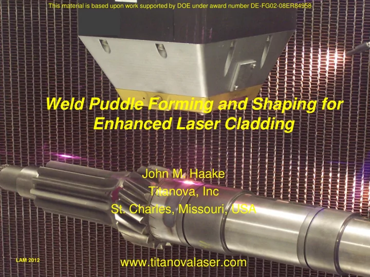
Weld Puddle Forming and Shaping for Enhanced Laser Cladding
John M. Haake Titanova, Inc
- St. Charles, Missouri, USA
www.titanovalaser.com
LAM 2012
This material is based upon work supported by DOE under award number DE-FG02-08ER84958