
SLIDE 1
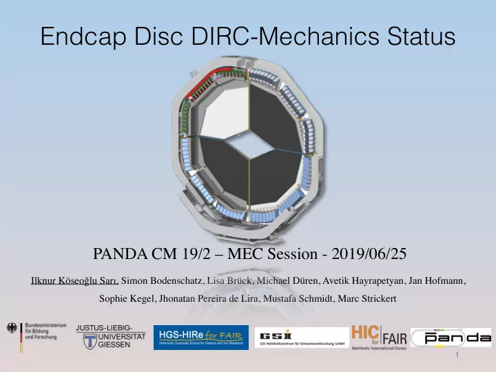
Endcap Disc DIRC-Mechanics Status
1
Ilknur Köseoğlu Sarı, Simon Bodenschatz, Lisa Brück, Michael Düren, Avetik Hayrapetyan, Jan Hofmann, Sophie Kegel, Jhonatan Pereira de Lira, Mustafa Schmidt, Marc Strickert
Endcap Disc DIRC-Mechanics Status PANDA CM 19/2 MEC Session - - - PowerPoint PPT Presentation
Endcap Disc DIRC-Mechanics Status PANDA CM 19/2 MEC Session - 2019/06/25 Ilknur Kseo lu Sar, Simon Bodenschatz, Lisa Brck, Michael Dren, Avetik Hayrapetyan, Jan Hofmann, Sophie Kegel, Jhonatan Pereira de Lira, Mustafa Schmidt, Marc
1
Ilknur Köseoğlu Sarı, Simon Bodenschatz, Lisa Brück, Michael Düren, Avetik Hayrapetyan, Jan Hofmann, Sophie Kegel, Jhonatan Pereira de Lira, Mustafa Schmidt, Marc Strickert
2
ROM
3
Rigid-flex PCB ROM case
HV Divider
Optical link
Alignment of 8 ROMs
4
ROM positions differ for each ROM.
5
Crates Legs Legs Insulation
6
Bar Focusing element EMC Insulation Support frame Crates
Optical link HV cables
7
Crates Crates Legs Legs Legs Insulation
7
8
Optical link cage HV cables Cooling pipe for ASICs
9
Insulation
10
11
7 ROMs design
12
LV cables HV cables
HV divider
13
14
15
ROM Case Rigid-PCB Rigid-PCB Flex-PCB HV-Divider HV-Cables