Enabling Topological Flexibility for Data Centers Using OmniSwitch - - PDF document

enabling topological flexibility for data centers using
SMART_READER_LITE
LIVE PREVIEW

Enabling Topological Flexibility for Data Centers Using OmniSwitch - - PDF document

Enabling Topological Flexibility for Data Centers Using OmniSwitch Yiting Xia Mike Schlansker T. S. Eugene Ng Jean Tourrilhes Rice University HP Labs Rice University HP Labs Core) Abstract switch) Most data centers deploy fixed network


slide-1
SLIDE 1

Enabling Topological Flexibility for Data Centers Using OmniSwitch

Yiting Xia Rice University Mike Schlansker HP Labs

  • T. S. Eugene Ng

Rice University Jean Tourrilhes HP Labs Abstract

Most data centers deploy fixed network topologies. This brings difficulties to traffic optimization and network manage- ment, because bandwidth locked up in fixed links is not ad- justable to traffic needs, and changes of network equipments require cumbersome rewiring of existing links. We believe the solution is to introduce topological flexibility that allows dynamic cable rewiring in the network. We design the Om- niSwitch prototype architecture to realize this idea. It uses in- expensive small optical circuit switches to configure cable con- nections, and integrates them closely with Ethernet switches to provide large-scale connectivity. We design an example control algorithm for a traffic optimization use case, and demonstrate the power of topological flexibility using simulations. Our so- lution is effective in provisioning bandwidth for cloud tenants and reducing transmission hop count at low computation cost.

1 Introduction

In traditional data centers, thousands of servers are con- nected through a multi-rooted tree structure of Ethernet

  • switches. Figure 1 depicts an example data center net-
  • work. At each layer of switches, the upstream bandwidth

is only a fraction of the downstream bandwidth, creating a bottleneck in the network core. Nowadays, novel net- work architectures with high bisection bandwidth have been studied to overcome this limitation [1, 17, 15]. Yet measurement studies show that the utilization of core links is highly imbalanced [18, 4], indicating mak- ing good use of the existing bandwidth is more critical than adding bandwidth to the network. A recent trend is to optimize the bandwidth utilization leveraging the di- verse routing paths in data centers. This set of works in- clude multi-path routing and transport protocols for load balancing [19, 25, 2, 29, 5, 31], flow scheduling mech- anisms for transmission acceleration [10, 9, 11, 8], and virtual tenant allocation heuristics for cloud service per- formance guarantees [16, 24, 3, 27, 21]. Besides routing flexibility, there is another level of flexibility that was rarely explored for bandwidth opti- mization: topological flexibility. Static network topolo- gies lock up bandwidth in fixed links, so congested links cannot get more bandwidth even if it exists in the net-

  • work. With a configurable network topology, bandwidth

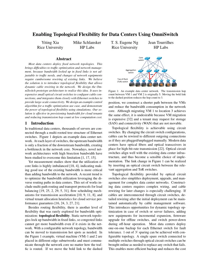
can be moved to transmission hot spots as needed. In the Figure 1 example, virtual machine (VM) 1 and 2 are placed in different edge subnetworks and must commu- nicate through the network core no matter how the traf- fic is routed. If we move the bold link to the dashed

Aggrega&on) switch)) Core) switch) Top3of3Rack) (ToR))switch))

3 2 3 1

Figure 1: An example data center network. The transmission hop count between VM 1 and VM 2 is originally 5. Moving the bold link to the dashed position reduces the hop count to 3.

position, we construct a shorter path between the VMs and reduce the bandwidth consumption in the network

  • core. Although migrating VM 1 to location 3 achieves

the same effect, it is undesirable because VM migration is expensive [32] and a tenant may request for storage (SAN) and connectivity (WAN) that are not movable. Topological flexibility is achievable using circuit

  • switches. By changing the circuit switch configurations,

cables can be rewired to different outgoing connections as if they are plugged/unplugged manually. Modern data centers have optical fibers and optical transceivers in place for high-bit-rate transmission [22]. Optical circuit switches align well with the existing data center infras- tructure, and thus become a sensible choice of imple-

  • mentation. The link change in Figure 1 can be realized

by inserting an optical circuit switch between the rele- vant aggregation and ToR switches. Topological flexibility provided by optical circuit switches also simplifies deployment, upgrade, and man- agement for complex data center networks. Construct- ing data centers requires complex wiring, and cable rewiring for later changes is especially challenging. If cables are interconnected through circuit switches, de- tailed rewiring after the initial deployment can be main- tained automatically by cable management software. This introduces opportunities for dynamic topology op- timization in case of switch or server failures, adding new equipments for incremental expansion, firmware upgrade for offline switches, and switch power-down during off-hour operation. Most data centers deploy

  • ne-on-one backup for each Ethernet switch for fault
  • tolerance. 1 out of N sparing can be achieved with con-

figurable topology. A single spare switch connected to multiple switches through optical circuit switches can be brought online as needed to replace any switch that fails. This enables more efficient backup and reduces the cost

slide-2
SLIDE 2

128 port x 5 Ethernet Stack

128 Ports

...

4x5 port x 128 Circuit Switch Stack Spare Switch Photonic Conversion Front View of OmniSwitch Panel

8 Multilink Connectors Multilink 16 x 25G Front Panel

Figure 2: Internal of an OmniSwitch cabinet

for redundancy significantly. In this paper, we present OmniSwitch, a configurable data center network architecture, and leverage its topo- logical flexibility to utilize and manage the data center

  • efficiently. OmniSwitch exploits cheap small port-count
  • ptical switches, such as 2D MEMS, Mach-Zehnder

switches, and switches using tunable lasers with ar- ray waveguide gratings, to minimize deployment costs. These switches are fabricated on a planar substrate us- ing lithography. Losses from photonic signal crossings

  • r other effects limit the port count to modest scale.

The mass production cost is dominated by packaging. With significant advances in photonic packaging, the per-port cost of these switches will be far cheaper than their counterparts that scale to thousands of ports. Be- cause small optical switches cannot provide general con- nectivity, building large-scale data centers requires inti- mate combination with the existing switching power in the network. OmniSwitch employs interleaving optical switches and Ethernet switches to provide topological flexibility for the full scope of a data center. Evalua- tions in Section 3.3 demonstrate small optical switches integrated in the OmniSwitch architecture are effective enough to give considerable topology flexibility. In the rest of the paper, we describe the OmniSwitch architecture and the control plane design. We use VM clustering as a case study and propose a control algo- rithm that enhances locality of traffic in the same ten-

  • ant. We evaluate our solution using simulations in the

tenant provisioning scenario. Compared to intelligent VM placement on a fixed network topology, running our VM clustering algorithm given dumb VM placement on the OmniSwitch configurable topology can reduce the rejected bandwidth by 60%. Our approach also reduces the provisioning time for large tenants from 17min to 1s.

2 OmniSwitch Design 2.1 Architecture

OmniSwitch deploys identical hardware building blocks to provision port count, bandwidth, and reliability. Fig- ure 2 illustrates an OmniSwitch module that combines electrical packet switches and optical circuit switches into a single cabinet. The Ethernet stack can be popu- lated with up to 5 cards each having a 128-port Ethernet

1 2 6 5 3 4 8 7 3 4 2 1 384 Port 768 Port 3 4 2 1

(a) (b)

Figure 3: OmniSwitch mesh network. The right subfigures show topologies of the Ethernet switches. Switch 1, 2, 3, 4 are in one cab- inet; switch 5, 6, 7, 8 are in another cabinet. Each line represents 4 individual fibers. Solid lines are connections within a cabinet; dashed lines are connections across cabinets.

switch ASIC. The 5th card is a spare switch to provide fault tolerance and always-on maintenance. The Ether- net switches are connected through electrical-to-optical converters, and then a stack of 4×5 photonic circuit switches, to optical front panel connectors. 16 25Gbps bidirectional fibers are bundled into one multilink to reduce the number of manually installed cables. Af- ter plugged into a multilink connector, these individual fibers are connected vertically across 16 adjacent opti- cal circuit switches. Each circuit switch allows arbitrary

  • ptical connections between a row of individual links in-

side the front panel and a corresponding row of Ethernet ports that span the Ethernet stack. Multilink connectors provide connectivity to both end devices (servers or ToR switches) as edge bandwidth and to other multilink con- nectors in the same or different OmniSwitch cabinets as core bandwidth. The proportion of core over edge band- width determines the oversubscription ratio. Mesh networks can be realized using single or multi- ple OmniSwitch cabinets. In Figure 3 (a), the 4 active Ethernet switches are each connected to other Ethernet switches through 2 multilinks. The remaining 384 in- dividual fiber ports can be used for end devices. Spe- cific connections among the Ethernet switches are de- cided by the circuit switch permutations. We present two possible topologies, where the total bandwidth be- tween switch pairs are adjustable depending on traffic

  • demand. Figure 3 (b) shows a larger network that gives

768 end-device ports. Ethernet switches in the same cab- inet connect to each other using 1 multilink each. They each also connect to switches in the other cabinet using 1 multilink. A possible topology is shown. OmniSwitch cabinets can also be structured as tree

  • networks. Spine cabinets are interior nodes in the tree

and only provide connectivity for the children cabinets. Leaf cabinets connect to both end devices and the par- ent spine cabinets. Figure 4 (a) is the topology used for our evaluations in Section 3.3. 4 leaf OmniSwitch cabinets each provide 8 upward and 24 downward mul- tilink ports. The dark and light lines show how uplink ports on leaf cabinets are connected to the spine cabinet.

slide-3
SLIDE 3

1 Spine OmniSwitch 4 Leaf OmniSwitches

32 uplink cables 1536 Port 3072 Port

(a) (b)

Figure 4: OmniSwitch tree network. In subfigure (b), the 2 uplinks out

  • f each cabinet refer to the 4 dark and light multilink connections in

subfigure (a) respectively.

In our example network, 8 ToR switches are connected to each multilink connector, each ToR switch having 2 25Gbps individual uplinks. A ToR switch hosts 8 servers each using a 25Gbps downlink. The network has 6144

  • servers. The ToR switches are 4:1 oversubscribed and

each cabinet provides 3:1 edge over core bandwidth, so the overall oversubscription ratio in the network is 12:1. Figure 4 (b) shows a 3072 port configuration using 8 leaf cabinets and 2 spine cabinets as a Clos topology. The leaf cabinets are connected to the core cabinets in a similar fashion to Figure 4 (a). The lines between the leaf and spine cabinets each represent 4 multilink cables. For each leaf cabinet, the two lines refer to the dark and light multilink connections in Figure 4 (a) respectively.

2.2 Advantage Discussion

Easy wiring: OmniSwitch reduces wiring complexity using multilink cables. Detailed interleaving for indi- vidual links are handled by circuit switch configuration

  • software. This enables automatic cable rewiring after a

hardware failure, during a switch firmware upgrade, or after partial power-down during off-hour operation. Incremental expansion: OmniSwitch cabinets can be partially populated with Ethernet switches and

  • servers. As new equipments are added to the cabinet, cir-

cuit switch settings are configured to adapt to the change, avoiding manual rewiring of existing links. As shown in Figure 3 and Figure 4, it is also simple to purchase addi- tional OmniSwitch cabinets to form larger networks. Efficient backup: As Figure 2 shows, by configu- ration the circuit switches, the 5th spare switch can be brought online to replace any Ethernet switch that fails. Compared to most data centers where each switch has a stand-by backup, OmniSwitch reduces the sparing hard- ware and achieves more efficient backup. Traffic optimization: Topological flexibility can en- hance traffic locality and reduce transmission hop count. Links that exchange the most traffic can be optically con- figured to a common Ethernet switch to minimize the traffic sent to higher layers in a network hierarchy. Op- posite to traffic locality, load balancing and failure re- silience can be achieved by optically directing traffic rel- evant to the same tenant to different Ethernet switches. Cost effectiveness: Small optical switches are poten- tially far cheaper than the large counterpart, despite less

  • flexibility. Circuit switches require one-to-one mapping

between the input and output ports. As Figure 2 depicts, the cables connected to the same optical switch cannot reach the same Ethernet switch. Evaluation result in Sec- tion 3.3 shows small optical switches can provide con- siderable topological flexibility, thus OmniSwitch makes a good tradeoff between configurability and cost.

2.3 Control Plane

The OmniSwitch architecture requires a control plane (1) to program optical switch connectivities for topol-

  • gy optimization and (2) to enforce routing for quick

adaptation to topology changes. Because a data center is administered by a single entity, an emerging trend is to leverage centralized network control to achieve global resource management [2, 26, 10]. We follow this trend to deploy a centralized network controller for OmniSwitch, which is a user process running on a dedicated machine in a separately connected control network. Most optical switches can be configured via a soft- ware interface, and existing works provide basic rout- ing mechanisms we can borrow. For example, after the topology is determined, our network controller can pre- compute the paths and program the routing decisions on switches using software-defined networking (SDN) pro- tocols [2, 5, 31] or VLANs [25, 30, 33], or on end hosts by source routing [16]. The control logic should be cus- tomized to different use cases, such as localizing traffic to save core network bandwidth, balancing workload to improve service availability, powering down some Eth- ernet switches to save energy, activating the spare Eth- ernet switch to recover from failure, etc. We design a control algorithm that configures topology and routing simultaneously for the VM clustering use case.

3 VM Clustering: A Case Study

In cloud computing terminology, tenant refers to a clus- ter of reserved VMs. A VM communicates with a subset

  • f other VMs in the same tenant; there is almost no com-

munication between VMs in different tenants [6]. VM clustering is to localize traffic within the same tenant by

  • ptically configuring end-device links that exchange the

most traffic to a common Ethernet switch. The algorithm requires no control of VM placement and seeks oppor- tunities for optimization in the network.

3.1 Problem Formulation

VM clustering can be realized at the flow level or the tenant level, reconfiguring the network either to address

slide-4
SLIDE 4

instant traffic changes at real-time or to address tenant bandwidth requirements that last for substantial time. We perform tenant management in this case study, be- cause frequent topology changes cause disruptions in the network and degrade transport performance. Ten- ant bandwidth requirements can be expressed by differ- ent network abstraction models [16, 12, 3, 21]. Here we use the simple pipe model that specifies bandwidth requirement between each VM pair as a Virtual Link (VL) [16, 24]. Other models apply to OmniSwitch as

  • well. The pipe model can be constructed either by user

specification or by bandwidth prediction tools [20]. Our problem is to place the VLs in the OmniSwitch network, so that maximum amount of bandwidth that tenants require can be hosted. Placing VLs on a fixed network topology can be formulated as a multi- commodity flow problem. Because splitting VLs across several physical links can cause packet reordering, we seek integer assignments to the problem, which is NP- complete [13]. In a configurable network like Om- niSwitch, there are numerous possible topologies, mak- ing the search space even larger. We design a heuristic algorithm to approximate the global optima.

3.2 Control Algorithm

For each tenant, the algorithm takes in the physical lo- cations of VMs and the bandwidth requirements of VLs. It accepts the tenant if it accommodates all the VLs with bandwidth guarantees, otherwise it rejects the tenant and recycles the allocated resources. We assume a tree struc- ture of OmniSwitch cabinets, as shown in Figure 4. The OmniSwitch cabinets run the same sub-procedure, layer by layer from the edge to the root of the tree. The output

  • f children cabinets is the input of parent cabinets.

In each cabinet, the algorithm handles VLs in the or- der of decreasing bandwidth requirement. Because con- figuring the optical switches can rewire cables to differ- ent Ethernet switches, we search through the egress and ingress uplinks with sufficient bandwidth on the source and destination VMs respectively to check what Ether- net switches can service the VL. If the egress and ingress uplink can reach up to the same Ethernet switch, the VL can be provisioned within this cabinet, demanding no extra bandwidth from the upstream cabinets. Optical cir- cuit switch allows an input port to be connected to only

  • ne output port, thus locating VLs from the same tenant
  • nto the same physical link saves optical ports for other
  • tenants. We use a scoring function for the VL uplink as-

signment, which favors links heavily utilized by the ten-

  • ant. If the VL must traverse different Ethernet switches,

e.g. optical ports connected to the same Ethernet switch

  • ccupied already, we place the VL on egress and ingress

uplinks with high scores and let the upstream cabinet deal with the connection between the Ethernet switches.

Table 1: Average hop count when load = 0.8 dumb +fixed Clos SecondNet +fixed Clos OmniSwitch OmniSwitch (big OCS) 4.622 4.164 3.217 3.048

3.3 Evaluation 3.3.1 Simulation Setup

To demonstrate the power of topological flexibility, we compare two solutions in a tenant provisioning scenario: dumb VM placement on the configurable topology vs. judicious VM placement on a static topology. For the first solution, we simulate the example OmniSwitch ar- chitecture in Figure 4 (a). When a tenant is subscribed, we provision VMs by contiguous placement and run the VM clustering algorithm to accommodate bandwidth for

  • VLs. For the second solution, we simulate a Clos net-

work with the same number of Ethernet switches and servers, and run the SecondNet tenant provisioning al- gorithm [16]. We simulate dumb VM placement on the fixed network as the baseline of comparison. To analyze the effectiveness of small optical switches, we also com- pare the original OmniSwitch with an alternative imple- mentation using one big optical switch for each cabinet. The simulated networks have 6144 servers. Second- Net places VMs within tenant onto different servers. For fair comparison, we give each server the capacity to host a single VM in these experiments. Each simulation run consists of 1000 Poisson tenant arrivals and departures. The tenant size and bandwidth requirements are sampled from the Bing data center workload [6]. The mean ten- ant size (S) is 79 and the largest tenant has 1487 VMs. We keep the tenant duration time (T) fixed and vary the mean arrival rate (λ) to control the load on the data cen- ter, which is defined as S×λ×T

6144 , or the proportion of re-

quested over the total VM slots.

3.3.2 Simulation Results

The simulated networks have 12:1 oversubscription ra- tio, so tenants may be rejected due to lack of network ca-

  • pacity. In this casee, all bandwidth required by the VLs

are considered rejected. We define bandwidth rejection rate as the amount of rejected bandwidth relative to the total requested bandwidth. We use this metric to evalu- ate each solution’s efficacy to accommodate tenants. Figure 5 shows OmniSwitch rejects very little band- width even when the load is high, which demonstrates its effectiveness in localizing traffic given the simple VM

  • placement. The OmniSwitch implementation using big
  • ptical circuit switches only reduces the rejection rate

slightly, indicating small optical switches can provide considerable topological flexibility. SecondNet is much better than the dumb solution, because it pre-configures the servers into clusters by hop count and prioritizes small-hop-count clusters for VM placement. However, it

slide-5
SLIDE 5

0.1 0.2 0.3 0.4 0.5 0.6 0.7 0.8 0.9 0.05 0.1 0.15 0.2 0.25 0.3 0.35 0.4 0.45 0.5 Load Bandwidth Rejection Rate dumb + fixed Clos SecondNet + fixed Clos OmniSwitch OmniSwitch (big OCS)

Figure 5: Average bandwidth rejection rate under different load

still rejects over 2× as much bandwidth as OmniSwitch. On the fixed topology, if a cluster cannot host the entire tenant, SecondNet must move to large hop-count clus- ters for resources. OmniSwitch utilizes bandwidth more efficiently by constructing connections dynamically ac- cording to bandwidth requirement of individual VLs. We measure the average hop count of the provi- sioned VLs to help interpret the above results. As shown in Table 1, the average hop count on the OmniSwitch network is significantly shorter than that of the Second- Net solution, which explains why OmniSwitch can host a lot more requested bandwidth. Big optical switches further reduce the hop count, but the bandwidth rejection rate in Figure 5 makes little difference. This is because OmniSwitch successfully reduces path length for most VLs, leaving sufficient core bandwidth for the rest VLs. In Figure 6, we compare the computation time of the SecondNet algorithm and the OmniSwitch VM clus- tering algorithm. OmniSwitch can finish provisioning a large tenant with over 1000 VMs in around 1s, and the computation time is not sensitive to variation of load; while SecondNet takes up to 17min and the computa- tion time grows significantly as the load increases. Al- though SecondNet pre-clusters the data center to reduce the problem size, it still needs to do exhaustive search in each cluster. This is quite expensive, especially when the servers are heavily occupied. The search space for the OmniSwitch VM clustering algorithm is very small. Since it seeks optimization for pre-allocated VMs, it

  • nly needs to search through a few uplinks and possible
  • ptical switch connections. Table 1 shows the algorithm

keeps most traffic within edge cabinets even at high load, so the search space does not enlarge with load increase.

4 Related Work

OmniSwitch is related to other configurable data cen- ter architectures using optical interconnects. Helios and c-Through construct a separate optical network with an expensive high port-count 3D MEMS side by side with the existing data center to add core bandwidth

  • n the fly [14, 33].

This idea is extended to differ- ent traffic patterns other than point-to-point communi- cation [34, 35]. OSA introduces WDM and WSS tech-

10

1

10

2

10

3

10

2

10

3

10

4

10

5

10

6

10

7

10

8

10

9

10

10

Tenant Size (#VM) Computation Time (us)

SecondNet − load = 0.2 SecondNet − load = 0.5 SecondNet − load = 0.8 OmniSwitch − load = 0.2 OmniSwitch − load = 0.5 OmniSwitch − load = 0.8

Figure 6: Algorithm computation time for various tenant size and load

nologies to provide multi-hop forwarding and tunable link capacity [7]. Mordia and Quartz use fast optical circuit switches (WSS or WDM rings) to build a full- mesh aggregation layer that has high bandwidth capac- ity and low switching latency [28, 23]. Because WSS and WDM rings scale poorly, these designs work best for small networks with tens of aggregation ports. OmniSwitch’s design goals are fundamentally differ-

  • ent. First, OmniSwitch aims to utilize existing band-

width resources efficiently, as opposed to adding band- width to the network. Second, we are the first to use small optical switches and integrate them with Ether- net switches to build modular building blocks that easily scale to the full scope of a large data center. Third, unlike prior work that configure optical switches to route traf- fic flows, OmniSwitch uses optical switches to optimize topology and leaves routing to Ethernet switches. It does not require real-time circuit construction for traffic for- warding, so the topology can be changed at coarser time scale to address tenant and network management needs.

5 Conclusion

This paper presents OmniSwitch, a modular data center network architecture that integrates small optical circuit switches with Ethernet switches to provide both topo- logical flexibility and large-scale connectivity. Mesh and tree networks can be easily constructed with identi- cal OmniSwitch building blocks. Topological flexibility can improve traffic optimization and simplify network

  • management. We demonstrate its potential with the VM

clustering case study, where we give a control algorithm that optimizes both topology and routing to enhance lo- cality of traffic within tenant. Our approach is evalu- ated using simulations driven by a real data center work-

  • load. Compared to the state-of-the-art solution, it re-

duces the average path length significantly and services more bandwidth using minimal computation time. Small

  • ptical switches are proven to provide similar topologi-

cal flexibility to a high port-count counterpart.

Acknowledgment

This research was sponsored by the NSF under CNS- 1422925, CNS-1305379 and CNS-1162270.

slide-6
SLIDE 6

* Discussion Topics

We are looking for feedback in a number of areas. We want outside evaluation of our progress including criti- cism or support that weakens or strengthens the excite- ment and importance of this work. We are looking for ideas that might broaden our future investigation or ideas for new applications for architectures with topological

  • flexibility. We welcome suggestions about alternatives

to our OmniSwitch design. We make a controversial assumption that ease and flexibility of network management have been tradition- ally underemphasized. Management includes physical management such as network deployment, network up- grade, and cable management as well as logical manage- ment including performance optimization, management for low power, fault tolerance, and on-line firmware up- grade. We introduce topological flexibility and Om- niSwitch as architectural tools to address these issues. Flexibility comes with its costs and we defend a con- troversial position that large rewards from management flexibility can justify costs for providing that flexibility. An interesting discussion debates relative merits of side-by-side versus integrated architectures for deploy- ing circuit switches with packet-switches. Side-by-side architectures may require highly dynamic elephant flow recognition. Elephant flows are not the only source for non-uniform traffic, and integrated architectures with topological flexibility may exploit new sources of non- uniform traffic. Integrated approaches may be successful even when elephant flows are not present. A number of open issues remain. This work needs commercially successful small port count photonic cir- cuit switches. While a number of candidate photonic architectures exist, no products are available today. We are interested in research to enhance control-plane ar- chitectures for the needs of topological flexibility. These control-plane architectures react quickly to changes in the underlying topology without disruption to running workloads.

References

[1] M. Al-Fares, A. Loukissas, and A. Vahdat. A Scalable, Com- modity Data Center Network Architecture. In SIGCOMM ’08, pages 63–74, Seattle, WA, 2008. [2] M. Al-fares, S. Radhakrishnan, B. Raghavan, N. Huang, and

  • A. Vahdat. Hedera: Dynamic Flow Scheduling for Data Cen-

ter Networks. In NSDI ’10, San Jose, CA, 2010. [3] H. Ballani, P. Costa, T. Karagiannis, and A. Rowstron. Towards Predictable Datacenter Networks. In SIGCOMM ’11, pages 242– 253, Toronto, Ontario, Canada, 2011. [4] T. Benson, A. Anand, A. Akella, and M. Zhang. Understanding Data Center Traffic Characteristics. SIGCOMM CCR, 40(1):92– 99, Jan. 2010. [5] T. Benson, A. Anand, A. Akella, and M. Zhang. MicroTE: Fine Grained Traffic Engineering for Data Centers. In CoNEXT ’11, pages 8:1–8:12, Tokyo, Japan, 2011. ACM. [6] P. Bod´ ık, I. Menache, M. Chowdhury, P. Mani, D. A. Maltz, and

  • I. Stoica. Surviving Failures in Bandwidth-Constrained Data-
  • centers. In SIGCOMM ’12, pages 431–442, Helsinki, Finland,

2012. [7] K. Chen, A. Singla, A. Singh, K. Ramachandran, L. Xu,

  • Y. Zhang, X. Wen, and Y. Chen. OSA: An Optical Switching Ar-

chitecture for Data Center Networks with Unprecedented Flexi-

  • bility. In NSDI ’12, San Joes, CA, April 2012.

[8] M. Chowdhury, S. Kandula, and I. Stoica. Leveraging Endpoint Flexibility in Data-Intensive Clusters. In SIGCOMM ’13, pages 231–242, Hong Kong, China, 2013. [9] M. Chowdhury and I. Stoica. Coflow: A Networking Abstraction for Cluster Applications. In HotNets-XI, pages 31–36, Redmond, WA, 2012. [10] M. Chowdhury, M. Zaharia, J. Ma, M. I. Jordan, and I. Stoica. Managing Data Transfers in Computer Clusters with Orchestra. In SIGCOMM ’11, pages 98–109, Toronto, Ontario, Canada, 2011. [11] M. Chowdhury, Y. Zhong, and I. Stoica. Efficient Coflow Scheduling with Varys. In SIGCOMM ’14, pages 443–454, Chicago, IL, 2014. [12] N. G. Duffield, P. Goyal, A. Greenberg, P. Mishra, K. K. Ramakr- ishnan, and J. E. van der Merive. A Flexible Model for Resource Management in Virtual Private Networks. In SIGCOMM ’99, pages 95–108, Cambridge, MA, 1999. [13] S. Even, A. Itai, and A. Shamir. On the Complexity of Time Table and Multi-commodity Flow Problems. In SFCS ’75, pages 184–193, Washington, DC, 1975. [14] N. Farrington, G. Porter, S. Radhakrishnan, H. H. Bazzaz,

  • V. Subramanya, Y. Fainman, G. Papen, and A. Vahdat. Helios: A

Hybrid Electrical/Optical Switch Architecture for Modular Data

  • Centers. In SIGCOMM ’10, pages 339–350, New Delhi, India,
  • Aug. 2010.

[15] C. Guo, G. Lu, D. Li, H. Wu, X. Zhang, Y. Shi, C. Tian, Y. Zhang, and S. Lu. BCube: A High Performance, Server-Centric Net- work Architecture for Modular Data Centers. In SIGCOMM ’09, pages 63–74, Barcelona, Spain, 2009. [16] C. Guo, G. Lu, H. J. Wang, S. Yang, C. Kong, P. Sun, W. Wu, and Y. Zhang. SecondNet: A Data Center Network Virtualization Architecture with Bandwidth Guarantees. In CoNEXT ’10, pages 15:1–15:12, Philadelphia, PA, 2010. [17] C. Guo, H. Wu, K. Tan, L. Shi, Y. Zhang, and S. Lu. Dcell: A scalable and fault-tolerant network structure for data centers. In SIGCOMM ’08, pages 75–86, Seattle, WA, 2008. [18] S. Kandula, S. Sengupta, A. Greenberg, P. Patel, and R. Chaiken. The Nature of Data Center Traffic: Measurements & Analysis. In IMC ’09, pages 202–208, Chicago, IL, 2009. [19] C. Kim, M. Caesar, and J. Rexford. Floodless in SEATTLE: A Scalable Ethernet Architecture for Large Enterprises. In SIG- COMM ’08, SIGCOMM ’08, pages 3–14, Seattle, WA, 2008. [20] K. LaCurts, J. C. Mogul, H. Balakrishnan, and Y. Turner. Ci- cada: Introducing Predictive Guarantees for Cloud Networks. In HotCloud’14, pages 14–19, Philadelphia, PA, 2014. [21] J. Lee, Y. Turner, M. Lee, L. Popa, S. Banerjee, J.-M. Kang, and

  • P. Sharma. Application-driven Bandwidth Guarantees in Data-
  • centers. In SIGCOMM ’14, pages 467–478, Chicago, IL, 2014.

[22] H. Liu, C. F. Lam, and C. Johnson. Scaling Optical Interconnects in Datacenter Networks Opportunities and Challenges for WDM. In HOTI ’10, pages 113–116, Mountain View, CA, 2010. [23] Y. J. Liu, P. X. Gao, B. Wong, and S. Keshav. Quartz: A New De- sign Element for Low-latency DCNs. In SIGCOMM ’14, pages 283–294, Chicago, IL, 2014. [24] X. Meng, V. Pappas, and L. Zhang. Improving the Scalabil- ity of Data Center Networks with Traffic-aware Virtual Machine

  • Placement. In INFOCOM’10, pages 1154–1162, San Diego, CA,

2010.

slide-7
SLIDE 7

[25] J. Mudigonda, P. Yalagandula, M. Al-Fares, and J. C. Mogul. SPAIN: COTS Data-center Ethernet for Multipathing over Arbi- trary Topologies. In NSDI’10, pages 18–33, San Jose, CA, 2010. [26] R. Niranjan Mysore, A. Pamboris, N. Farrington, N. Huang,

  • P. Miri, S. Radhakrishnan, V. Subramanya, and A. Vahdat. Port-

Land: A Scalable Fault-Tolerant Layer 2 Data Center Network

  • Fabric. In SIGCOMM ’09, pages 39–50, Barcelona, Spain, 2009.

[27] L. Popa, A. Krishnamurthy, S. Ratnasamy, and I. Stoica. Fair- Cloud: Sharing the Network in Cloud Computing. In HotNets-X, pages 22:1–22:6, Cambridge, MA, 2011. [28] G. Porter, R. Strong, N. Farrington, A. Forencich, P. Chen-Sun,

  • T. Rosing, Y. Fainman, G. Papen, and A. Vahdat. Integrating Mi-

crosecond Circuit Switching into the Data Center. In SIGCOMM ’13, pages 447–458, Hong Kong, China, 2013. [29] C. Raiciu, S. Barre, C. Pluntke, A. Greenhalgh, D. Wischik, and

  • M. Handley.

Improving Datacenter Performance and Robust- ness with Multipath TCP. In SIGCOMM ’11, pages 266–277, Toronto, Ontario, Canada, 2011. [30] M. Schlansker, Y. Turner, J. Tourrilhes, and A. Karp. Ensemble Routing for Datacenter Networks. In ANCS ’10, pages 23:1– 23:12, La Jolla, CA, 2010. [31] B. Stephens, A. Cox, W. Felter, C. Dixon, and J. Carter. PAST: Scalable Ethernet for Data Centers. In CoNEXT ’12, pages 49– 60, Nice, France, 2012. [32] W. Voorsluys, J. Broberg, S. Venugopal, and R. Buyya. Cost

  • f Virtual Machine Live Migration in Clouds: A Performance
  • Evaluation. In CloudCom ’09, pages 254–265, Beijing, China,

2009. [33] G. Wang, D. G. Andersen, M. Kaminsky, K. Papagiannaki,

  • T. S. E. Ng, M. Kozuch, and M. Ryan. c-Through: Part-time

Optics in Data Centers. In SIGCOMM ’10, pages 327–338, New Delhi, India, Aug. 2010. [34] H. Wang, Y. Xia, K. Bergman, T. E. Ng, S. Sahu, and K. Sri-

  • panidkulchai. Rethinking the Physical Layer of Data Center Net-

works of the Next Decade: Using Optics to Enable Efficient *- cast Connectivity. SIGCOMM CCR, 43(3):52–58, July 2013. [35] Y. Xia, T. S. E. Ng, and X. Sun. Blast: Accelerating High- Performance Data Analytics Applications by Optical Multicast. In INFOCOM’15, pages 1930–1938, Hong Kong, China, 2015.