
Roger Johansson/ 2010
Ti t i d l ti i ti Time triggered real time communication
Presentation overview
Background
automotive electronics, an application area for time triggered communication.
Time triggered protocols
TTPC, first commercial implementation. Originally from TU Vienna. Operational p g y p in civil aircrafts. TTCAN, based on Controller Area Network (CAN) which is widely used in today's vehicular electronic systems today s vehicular electronic systems. FlexRay, based on BMW’s “ByteFlight”. Anticipated in next generation automotive electronic systems.
Hybrid scheduling
combining static scheduling with fixed priority scheduling analysis.
Time triggered real time communication 1 Roger Johansson/ 2010
A premium passenger car is controlled and A premium passenger car is controlled and managed by 80+ Embedded Systems
Comfort Electronics: Thermal Management Chassis Control Infotainment: Telematics Solutions Car PC Wireless Connectivity Chassis Control Parking Assistant Wireless Connectivity Car-to-car communication Floating Car Data Po ertrain Powertrain: Engine Management Transmission Control Power Management Safety: Predictive Safety Systems Driver Assistance Systems Adaptive Cruise Control
Time triggered real time communication 2
g Adaptive Cruise Control Electric Power Steering
Courtesy of DaimlerChrysler, Bosch Roger Johansson/ 2010
Vi t l diff ti ti b t i t
Entertainment
Virtual differentiation between variants
- All variants of a specific
Variant 1
configuration A
model are physically identical and differ only in their individual software configuration
Motor configuration A
- The various included
physical components can be activated or deactivated by the software
Motor configuration Entertainment configuration F
the software
g B
Variant 2
Time triggered real time communication 3 Roger Johansson/ 2010
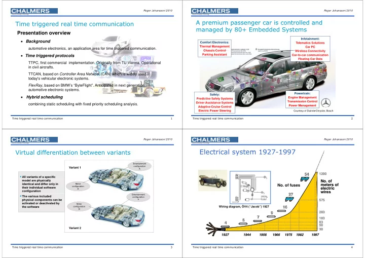
Electrical system 1927 1997 Electrical system 1927-1997
54 54
1200 1200
27 27
- No. of fuses
- No. of
- No. of
meters of meters of electric electric wires wires 16 16 27 27
575 575
wires
Wiring diagram, ÖV4 (“Jacob”) 1927
4 4 5 5 7 7 9 9 16 16
283 283 183 183 83 83
Wiring diagram, ÖV4 ( Jacob ) 1927
1927 1927 1975 1975 1982 1982 1944 1944 1997 1997 1966 1966 1956 1956
4 4
83 83 50 50 30 30 1927 1927 1975 1975 1982 1982 1944 1944 1997 1997 1966 1966 1956 1956
Time triggered real time communication 4