
SLIDE 1
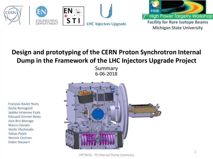
Design and prototyping of the CERN Proton Synchrotron Internal Dump in the Framework of the LHC Injectors Upgrade Project
Summary
François-Xavier Nuiry Giulia Romagnoli Jaakko Johannes Esala Edouard Grenier Boley Jose Briz Monago Marco Calviani Vasilis Vlachoudis Tobias Polzin Yannick Coutron Didier Steyaert
6-06-2018
HPTW18 - PS Internal Dump Summary 1