DISTRIBUTION TRANSFORMERS BUREAU OF INDIAN STANDARDS BHOPAL BIS - - PowerPoint PPT Presentation

distribution transformers
SMART_READER_LITE
LIVE PREVIEW

DISTRIBUTION TRANSFORMERS BUREAU OF INDIAN STANDARDS BHOPAL BIS - - PowerPoint PPT Presentation

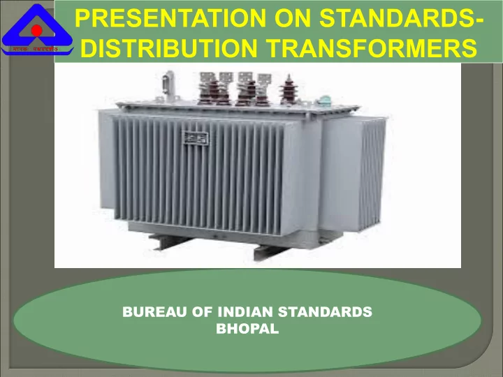
PRESENTATION ON STANDARDS- DISTRIBUTION TRANSFORMERS BUREAU OF INDIAN STANDARDS BHOPAL BIS Act WTO Principle on Standard Process for development of Indian Standard Standards on Transformers Detailed provision of IS 1180-1


slide-1
SLIDE 1

PRESENTATION ON STANDARDS- DISTRIBUTION TRANSFORMERS

BUREAU OF INDIAN STANDARDS BHOPAL

slide-2
SLIDE 2
  • BIS Act
  • WTO Principle on Standard
  • Process for development of Indian Standard
  • Standards on Transformers
  • Detailed provision of IS 1180-1
  • Proposed Changes in IS 1180-1
slide-3
SLIDE 3
  • National Standards Body constituted under

the Act of Parliament (1986)

  • New BIS Act 2016 has been notified
  • Indian Standards developed by BIS through

technical committee involving all concerned Stakeholders

  • BIS standard development process in

compliance with WTO-TBT principles

slide-4
SLIDE 4

WTO Agreements

Rules for international trade being written through various WTO Agreements

  • Rules pertaining to Standards, Regulations and

Conformity Assessment for Trade in Goods are laid down in: Agreement on Sanitary and Phyto Sanitary Measures (SPS) Agreement on Technical Barriers to Trade (TBT)

slide-5
SLIDE 5

Technical Regulation Standard Mandatory Measures Voluntary Measures Conformity Assessment Procedure

slide-6
SLIDE 6
  • Transparency
  • Openness
  • Impartiality and consensus
  • Effectiveness and relevance
  • Coherence
  • Development dimension

 Compliance of “Code of Good Practice for the

Preparation, Adoption and Application of Standards”

slide-7
SLIDE 7

1 1 14 322 509 Experts involved approx 15000

Bureau Standards Advisory Committee Division Councils Sectional Committees Panel/ Sub-Committees

Minister in Charge Minister of State Secretary of MoCA Director General + Other members appointed by Govt from GoVt, Industry, Scientific & research Institutions and other interests

Advisory Committee regulations 1987

1.Harmonious Development of Standards

  • 2. Establishment Publication and promotion of

Standards 3.Collaboration with SDO’s of Country and Abroad

  • 4. Formulation of guidelines for effective

functioning

  • f DC
  • 5. Other Matters regarding Standardization

Rule 7: Consumers, regulatory and other Government bodies, industry, scientists, technologists and testing organizations. These may also include consultants. An officer of the Bureau shall be the Member Secretary.

DG + 9 members Ministry – 2 Consumer – 1 Industry/trade – 2 Scientific/ research – 1 Technical/ Educational- 1 Bureau members -2 : Plus 9 Special invitees

GOVERNANCE FRAMEWORK

slide-8
SLIDE 8

Areas of Standardization

Chemical Civil Engineering Electronics and Information Technology Electro-technical Food and Agriculture Management and Systems Mechanical Engineering Medical Equipment and Hospital Planning Metallurgical Engineering Petrochemical, Coal & Related Products Production and General Engineering Textiles Transport Engineering Water Resources

Bureau of Indian Standards (BIS)

slide-9
SLIDE 9

International Training Programme, 10 May 2012

Stage 2 : Building consensus among committee members Stage 3: Building national consensus

Stages of Standards Formulation

Bureau of Indian Standards (BIS)

BIS Procedure compliant to WTO-TBT Code of Practice

slide-10
SLIDE 10

Priority I

12 Months

Priority

II 24 Months

slide-11
SLIDE 11

51% 17% 11% 3% 4% 14%

Product standards Test methods Codes of practice Terminology Dimensions & Symbols Others

Product Standards 9450 Test Methods Others

Standards as on date 19300

Code of Practice

slide-12
SLIDE 12

COMPOSITION

  • f

STANDARD FORMULATION COMMITTEE

Chairman (Independent Body) Member Secretary (BIS) Manufacturer Laboratories/ R&D Institutions Government & Regulatory Bodies Consumer/ User Organization Industry Association Public Sector Units

Consulting Firms

Professional & Academic Bodies

slide-13
SLIDE 13

13

FIRST DRAFT CIRCULATION TO COMMITTEE MEMBERS

P-DRAFT

COMMENTS

CIRCULATION TO COMMITTEE MEMBERS

COMMENTS

PUBLIC CIRCULATION +Web (30 to 90 Days)

COMMENTS

NATIONAL STANDARD

NEW WORK ITEM

MEETING WC DRAFT

ADOPTION BY DIVISION COUNCIL

F-DRAFT STANDARD

MEETING

slide-14
SLIDE 14
  • ETD 16 – Transformers
  • 40 Standards published
  • Power Transformer
  • Distribution Transformer
  • Dry type transformer
  • Accessories/Fittings
  • Reactors
  • Voltage Corrrector
  • Tap Changer
  • Code for selection, installation and

maintenance

slide-15
SLIDE 15

EARLIER INDIAN STANDARDS ON DISTRIBUTION TRANSFORMERS

  • IS 1180(Part 1): 1989: Outdoor type three phase

distribution transformers upto and including 100kVA 11 kV Part 1: Non sealed type.

  • IS 1180(Part 2): 1989: Outdoor type three phase

distribution transformers upto and including 100kVA 11 kV Part 2: Sealed type.

  • Scope was limited upto three phase 100 kVA, 11kV.
slide-16
SLIDE 16
  • The main objective in formulation of IS1180 Part 1 was to

bring uniformity in technical specifications of DTs by various stakeholders in power industry.

  • IS1180 is a National Standard formulated by BIS, taking

into account needs of Stakeholders and various guidelines issued by Ministry of Power, Ministry of Heavy Industries, Ministry of Commerce, CEA, REC, BEE and various Electricity Boards/Discoms.

  • All the stakeholders need to respect the standard in toto

unless there is a serious objection which is impractical to achieve or implement.

NEED AND OBJECTIVE FOR REVISION

slide-17
SLIDE 17

REVISED VERSION OF IS ON DISTRIBUTION TRANSFORMERS

  • IS 1180(Part 1) - Outdoor type, insulated

liquid immersed Distribution Transformers up to and including 2500 kVA, 33kV (Part 1: Mineral Oil Immersed)

  • Published in 2014
slide-18
SLIDE 18

SALIENT FEATURES OF IS 1180(Part 1): 2014

SCOPE Includes Outdoor type three phase Distribution Transformers upto and including

2500 kVA with nominal system voltage upto and including 33 kV (both sealed and non-sealed)

  • Includes Single phase Distribution Transformers upto and including 25 kVA

(sealed type) Proposed Amendment No. 1

  • To include indoor type transformers
  • relevant CEA guidelines must be followed while using mineral oil filled

DT’s indoor.

  • In case of indoor transformers and transformers installed in an

enclosure, suitable ventilation, if required, shall be provided to maintain service conditions as per IS 2026 (Part 1).

slide-19
SLIDE 19

WHAT IS A DISTRIBUTION TRANSFORMER

  • As per definition, DTs are meant for stepping down voltage used in distribution

lines to the levels used by the customers

  • Transformer with Primary voltage of 3.3, 6.6, 11, 22 or 33 kV and secondary

voltage of 433 Volt, 3 Phase (250 volt for single phase ) are called Distribution Transformers.

Proposed Amendment No. 1

  • Amended definition of Distribution Transformer — A distribution transformer is a

transformer that provides the final voltage transformation by stepping voltages down within a distribution circuit or from a distribution circuit to an end user or application.

  • NOTE —The distribution circuit voltages are 3.3 kV, 6.6 kV, 11 kV, 22 kV and 33 kV in the
  • country. The power supply for the end users is 415 volt, 3 Phase (240 volt, 1 phase), 50 Hz.

Transformers with primary voltages of 3.3, 6.6, 11, 22 or 33 kV and secondary voltage of 433 volt, 3 Phase (and 250 volt single phase) are called Distribution Transformers. The maximum rating of these transformers for the purpose of this standard is considered up to 2 500 kVA, 3 Phase.’

slide-20
SLIDE 20

LIST OF STANDARDS NOT COVERED

To clarify and for ease in implementation, following exclusion list is being added through Amendment No. 1: a) Inverter duty transformers; b) Traction transformers; c) Instrument transformers; d) Transformers for static converters; ▫ e) Starting transformers ▫ f) Testing transformers; ▫ g) Welding transformers; ▫ h) Earthing transformers;

  • i) Mining transformers;
  • j) Transformers for solar, wind power application;
  • k) Transformers for railways (locomotive and other applications);
  • l) Furnace transformers;
  • m) Rectifier transformers; and
  • n) Dual ratio in primary/secondary windings transformers
slide-21
SLIDE 21

RATING

Given in Tables 1, 4, 7:

  • Preferred
  • Non-preferred (Maximum total losses are subject to agreement between

the user and the supplier) Proposed Amendment No. 1

  • Following ratings are being added through amendment no. 1:

a) Preferred rating: 800 kVA (3 phase, upto 33 kV) b) Non preferred ratings: 50 kVA, 75 kVA, 100 kVA (single phase, 11 kV, 22 kV, 33 kV)

slide-22
SLIDE 22

BASIC INSULATION LEVEL

  • Rated BIL values for Nominal System Voltages are

given in Table 2, Table 5 and Table 8. Propose Amendment No. 1

  • The BIL values as minimum values. However,

insulation coordination of all relevant fitting corresponding to higher BIL may be ensured.

slide-23
SLIDE 23
  • No taps are generally required upto 100 kVA, unless

specified

  • Standard tapping range is given below:

Transformer range

  • No. of tap

positions Voltage variation 3 phase transformers upto and including 200 kVA 4 +2.5% to -5% of HV in steps of 2.5 percent 3 phase transformers higher than 200 kVA and upto and including 2500 kVA 7 +5% to -10% of HV in steps of 2.5 percent for variation of HV NOTE: 1) For ratings greater than 500 kVA, on load tap changers may be provided for variation of HV voltage from +5 percent to –15 percent in steps of 2.5 percent 2) Off-circuit tap-changing is permitted

TAPPINGS

Proposed Amendment no. 1

  • It has been decided to make the provision of Tappings (both range and steps)

subject to agreement between the user and the supplier for which amendment is being issued.

slide-24
SLIDE 24
  • Losses given in Table 3, Table 6 and Table 9 are

MAXIMUM total losses

  • These losses are only for transformers upto 11kV

voltage class

  • For 22 kV and 33 kV class higher losses values

permitted

  • No load losses are dependent on so many factors

including design, therefore not given separately Proposed Amendment no. 1

  • Losses for non-preferred ratings have been added

through amendment which is being issued.

LOSSES

slide-25
SLIDE 25
  • Maximum total losses for voltage class above 11 kV is

given in table below:

Voltage class Maximum total losses for 3 phase transformers upto and including 200 kVA Maximum total losses for 3 phase transformers higher than 200 kVA and upto and including 2500 kVA Maximum total losses for single phase transformers upto and including 25 kVA Above 11 kV and upto and including 22 kV Shall not exceed by 5% of the maximum total losses given in Table 3 Shall not exceed by 5% of the maximum total losses given in Table 6 Shall not exceed by 7.5% of the maximum total losses given in Table 9 Above 22 kV and upto and including 33 kV Shall not exceed by 7.5% of the maximum total losses given in Table 3 Shall not exceed by 7.5% of the maximum total losses given in Table 3 Shall not exceed by 10% of the maximum total losses given in Table 3

slide-26
SLIDE 26
  • Maximum Flux density variation shall not exceed

1.9 Tesla with voltage and frequency variation (Design calculation to be submitted)

  • No load current shall not exceed 2 % (3% for 1 Ph)
  • f full load current

NO LOAD CURRENT AND FLUX DENSITY No Amendment proposal

slide-27
SLIDE 27
  • Values of % impedance given in IS 1180 (Part 1) : 2014

are only RECOMMENDED values .

  • Manufacturers can prefer other while designing
  • Higher impedance values might lead to poor regulation,

more stray losses and heating, therefore small variation in these values can be made

% IMPEDENCE VALUES No Amendment proposal

slide-28
SLIDE 28

MARKING:

Proposed Amendment No. 1 Dimensions of Rating Plate, Terminal Marking Plate and Combined Rating and Terminal Plate have been made subject to agreement between the user and the supplier

MARKING PLATE DIMENSIONS

slide-29
SLIDE 29
  • Limits are given as below:

Transformer class Limits for temperature rise 3 phase transformers upto and including 200 kVA For transformer winding - 40°C (when measured by resistance method) For top oil - 35°C (measured by thermometer) 3 phase transformers higher than 200 kVA and upto and including 2500 kVA For transformer winding - 45°C (when measured by resistance method) For top oil - 40°C (measured by thermometer) single phase transformers upto and including 25 kVA For transformer winding - 40°C (when measured by resistance method) For top oil - 35°C (measured by thermometer)

LIMITS OF TEPERATURE RISE No Amendment proposal

slide-30
SLIDE 30
  • These are maximum limits of temperature rise
  • These limits in IS 1180 (Part 1) : 2014 are more stringent

compared to International standards

  • Lower temperature rise limits are acceptable but it might

increase the cooling equipment cost

LIMITS OF TEPERATURE RISE No Amendment proposal

slide-31
SLIDE 31

TERMINAL ARRANGEMENTS For Cable box, following provisions have been added through amendment:

  • bus duct arrangement may be provided on low voltage side by agreement

between the user and the supplier

  • Porcelain/ Epoxy/Silicon Rubber Bushing may also be used subject to

agreement between the user and the supplier.’  For bushings, following notes has been added through amendment:

  • For heavily polluted atmosphere, dimensions of bushings shall confirm to

IS 8603.

  • Cast resin or polymer bushing can also be used with performance

requirements as per IS 2099 and IS 7421 LV Bushing Voltage Class: It has been decided to change LV Bushing Voltage Class from 1.1 kV to 1 kV

slide-32
SLIDE 32
  • Specified clearances values are MINIMUM values
  • Clearances above these values are acceptable as per IS

1180 (Part 1) : 2014

  • Clearances between coils and no. of coils are not given

as these are design parameters

MINIMUM CLEARENCES IN AIR No Amendment proposal

slide-33
SLIDE 33
  • Mounting arrangement is given in cl 14
  • Bidirectional rollers can also be used as per mutual agreement between the user and

the supplier Proposed Amendment no. 1 a) Upto 200 kVA:

  • two channels of minimum size 75 mm × 40 mm shall be provided
  • Note added under Fig. 6 – Any other mounting dimensions are subject to

agreement between the user and the supplier b) Beyond 200 kVA

  • Preferred mounting dimensions given under table in Fig 7 have been

modified

  • Note added under Fig. 7 – Any other mounting dimensions are subject to

agreement between the user and the supplier

MOUNTING ARRANGEMENT

slide-34
SLIDE 34
  • Measuring Paint Thickness is not a part of the tests

specified in IS 1180 (Part 1).

  • This is for guidance for manufacturers only. It is to

be ensured by the Inspecting agencies at the time factory visit.

PAINT THICKNESS No Amendment proposal

slide-35
SLIDE 35

CONSTRUCTION REQUIREMENTS FOR TRANSFORMER TANK Proposed Amendment No. 1

  • Given under clause 15
  • Minimum thickness at the corrugations has been specified as 1.0 mm through

amendment

slide-36
SLIDE 36

Existing standard fitting

Changes to be made through amendment

Two earthing terminals with the earthing symbol =| ; No change Oil level gauge indicating oil level at minimum, 30°C and maximum operating temperature; NOTES 1 Minimum and maximum positions correspond to the operating temperature of –5°C and 90°C respectively (for non-sealed type transformer). 2 Minimum position corresponds to the operating temperature of 30°C (for sealed type transformers). Oil level gauge indicating oil level at minimum, 30°C and maximum operating temperature; NOTES 1 Minimum and maximum positions correspond to the

  • perating temperature of –5°C and 90°C respectively (for non-

sealed type transformer). 2 Only minimum position corresponding to the operating temperature of 30°C (for sealed type transformers). Air release device (for non-sealed type transformers) No change Rating and terminal marking plates; No change Plain breathing device for non-sealed type transformers which would not permit ingress of rain water and insects up to 200 kVA

  • transformers. Above 200 kVA transformers dehydrating

breather shall be provided Dehydrating breather shall be provided for non-sealed type transformers; Drain-cum-sampling valve (¾″ nominal size thread, IS 554) preferably steel with plug for three phase transformers; Drain-cum-sampling valve preferably steel with plug for three phase transformers (for ratings above 500 kVA); NOTE — Valve size shall be as per agreement between the user and the supplier.

CHANGES IN STANDARD FITTINGS given under clause 20.1

slide-37
SLIDE 37

Existing standard fitting Changes to be made through amendment Thermometer pocket with cap; No Change Oil filling holes having (1¼″ nominal size thread) with cover (for sealed type transformers without conservator) Oil/Nitrogen/Air filling hole having (1¼″ nominal size thread) with cover (for sealed type transformers without conservator); An extended pipe connection on upper end with welded cover for sealed type transformers. The pipe should be suitably threaded over a sufficient length to enable use of a refilling/siphon connection after removing the welded cover or any other similar arrangement capable of reuse; Deleted Lifting lugs for the complete transformer as well as for core and winding assembly; No Change Nitrogen/air filling device/pipe with welded cover capable of reuse (for sealed type transformer); Deleted Pressure relief device or explosion vent above 200 kVA; Pressure relief device or explosion vent [for sealed type transformers (for all ratings) and non-sealed type transformers (for ratings above 200 kVA)]; One filter valve on the upper side of the tank (for transformers above 200 kVA); No Change Unidirectional flat rollers (for transformers above 200 kVA) Deleted Inspection hole (for transformers above 200 kVA); Deleted Pressure gauge for sealed transformers with radiators and nitrogen cushion (above 200 kVA); Deleted HV side neutral grounding strip (where one of the HV bushing terminal is connected to earth); No Change LV earthing arrangement for single phase transformers; No Change Buchholz relay for transformers above 1 000 kVA. No Change New fittings added Arcing horns for HT side (one number per phase)

slide-38
SLIDE 38

CHANGES IN OPTIONAL FITTINGS given under clause 20.2:

Existing Optional fittings Changes Filter valve (1¼″ nominal size thread) for transformers up to 200 kVA; Filter valve for transformers up to 200 kVA; NOTE — Valve size shall be as per agreement between the user and the supplier.’ Arcing horns or suitable rating lightning arrestors for HT side – 3

  • Nos. for transformers up to 200 kVA;

‘c) Suitable rating lightning arrestors for HT side (one number per phase);’ Pressure relief device or explosion vent (up to 200 kVA) Pressure relief device or explosion vent (upto 200 kVA for non-sealed type transformers); Protection relay for sealed type transformers for internal parameters that is pressure, temperature, oil level and gas detection (above 1 000 kVA) Protection relay for sealed type transformers for internal parameters that is pressure, temperature, oil level and gas detection New Fittings ‘q) Unidirectional flat rollers (for transformers above 200 kVA); r) Drain-cum-sampling valve preferably steel with plug for three phase transformers (for transformers upto 500 kVA); and NOTE — Valve size shall be as per agreement between the user and the supplier. s) Self protection/disconnection devices subject to agreement between the user and the supplier: 1) Thermo-magnetic circuit breaker as self protection device on secondary side as per IS/IEC 60947-2 : 2003; and 2)Expulsion fuse as disconnection device on primary side as per IS 9385 (Part 2): 1980. NOTE— Additional requirements for transformers with self protection/disconnection devices are under preparation.’

slide-39
SLIDE 39

Proposed Amendment No. 1 -CHANGES IN TEST REQUIREMENTS

a) ROUTINE TESTS

  • Separate-source voltage withstand test: Following note has been added

under this test: ‘For single phase transformer with 11/√3 or 22 / √3 or 33/√3 kilo volts and with 1.0 kV neutral bushing, this test shall be conducted at test voltage of neutral (3 kV rms for one minute).’

b) TYPE TESTS

  • Temperature-rise test: Note given under this test was deleted.
  • Pressure test

a) Upto 200 kVA:

  • Test requirements for corrugated tanks added
  • Limits of deflection of flat plates from 1251 mm to 1750 mm has been added
  • Note added that permanent deflection is not applicable for corrugations
slide-40
SLIDE 40

Proposed Amendment No. 1 b) Beyond 200 kVA

  • Test requirements for corrugated tanks added
  • Note added that permanent deflection is not applicable for corrugations
  • Leakage test

Annexure providing additional information on Leakage test has been added. SPECIAL TESTS

  • These are to conducted on one unit and shall be subject to agreement between user and

supplier

  • Paint adhesion test and BDV and moisture content on oil in the transformer may be carried
  • ut on more than one unit subject to agreement between user and the supplier
slide-41
SLIDE 41

METHOD OF DECLARING EFFICIENCY The efficiency to be declared is the ratio of the output in kW to the input in kW and calculated as under. Efficiency = output/input = input- total losses/ input Total losses comprise: No-load loss, which is considered to be constant at all loads : and Load loss, which varies with load. The total loss, on load is the sum of above losses.

slide-42
SLIDE 42