
SLIDE 1
Distributed Series Reactor
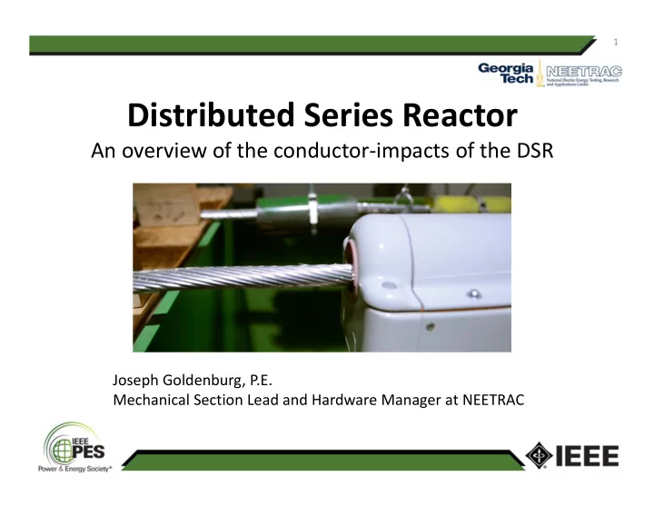
An overview of the conductor‐impacts of the DSR
1
Joseph Goldenburg, P.E. Mechanical Section Lead and Hardware Manager at NEETRAC
Distributed Series Reactor An overview of the conductor impacts of - - PowerPoint PPT Presentation
1 Distributed Series Reactor An overview of the conductor impacts of the DSR Joseph Goldenburg, P.E. Mechanical Section Lead and Hardware Manager at NEETRAC 2 Table of Contents DSR Technology Overview History NEETRAC Testing
1
Joseph Goldenburg, P.E. Mechanical Section Lead and Hardware Manager at NEETRAC
2
3
1.
Autonomously, based on locally programmable set points
2.
Two way communication, enabling more sophisticated operation and line monitoring
4
2009 2010 2011 2012 2013 2014 2001‐2008
DSR Prototype Initial Patent Filing
Formation of the Smart Wire Focus Initiative (SWFI)
Formation of the Smart Wire Grid, Inc. (SWG)
NEETRAC Gen 1 Testing NEETRAC Gen 2 Testing
99 units installed at TVA 33 units installed at Southern Company
5
6
7
8
9
DSR Type Sample ID Sample Test Run Initial Slip Load (lb)
1000 32013‐002‐10 1 1 445 2 495 3 518 32313‐002‐10 2 1 525 2 520 3 540 3213‐003‐10 3 1 455 2 530 3 500 1500 3213‐002‐15 4 1 620 2 555 3 700 32013‐002‐15 5 1 627 2 648 3 678 32313‐001‐15 6 1 570 2 680 3 525
10
11
12
13
14
4200 lb tension, Unit Placed 6 ft 10 in From Termination
42 40 38 36 34 32 30 28 26 24 22 20 18 16 14 12 10 8 6 4 0.026 0.024 0.022 0.020 0.018 0.016 0.014 0.012 0.010 0.008 0.006 0.004 0.002 0.000 Frequency ( Hz) Relat ive Displacement ( in)
1 2 3 Meter
42 40 38 36 34 32 30 28 26 24 22 20 18 16 14 12 10 8 6 4 0.026 0.024 0.022 0.020 0.018 0.016 0.014 0.012 0.010 0.008 0.006 0.004 0.002 0.000 Frequency ( Hz) Relat ive Displacement ( in)
1 2 3 Meter
42 40 38 36 34 32 30 28 26 24 22 20 18 16 14 12 10 8 6 4 0.026 0.024 0.022 0.020 0.018 0.016 0.014 0.012 0.010 0.008 0.006 0.004 0.002 0.000 Frequency ( Hz) Relat ive Displacement ( in)
1 2 3 Meter
42 40 38 36 34 32 30 28 26 24 22 20 18 16 14 12 10 8 6 4 0.026 0.024 0.022 0.020 0.018 0.016 0.014 0.012 0.010 0.008 0.006 0.004 0.002 0.000 Frequency ( Hz) Relat ive Displacement ( in)
1 2 3 Meter
No Damper (Config. 13)
Damper at 9 ft ( Config. 15)
Damper at 8 ft 6 in (Config. 14) Damper at 9 ft 6 in (Config. 16)
15
16
17
18
19
20
21
22
23
Date DSR Type DSR SN kA (rms) Results 11/20/2013 1000 32013-001-10-02A-0 68.9 Passed 11/20/2013 1000 32013-003-10-02A-0 69 Passed 11/21/2013 1000 32013-002-10-02A-0 68.4 Passed 11/21/2013 1500 32013-001-15-02A-0 68.8 Passed 11/21/2013 1500 32013-003-15-02A-0 68.6 Passed 11/21/2013 1500 32013-002-15-02A-0 68.8 Passed
24
Sample_Volt
1 27.74 V 2 -34.17 V
91.1 V
Sample_Curr_Z
1 -157.7 kAmp 2 -13.58 kAmp
215.0 kAmps
2.000s/div 02:12.9 02:24.1
02:14.3790372 External Trigger 1 02:14.3874998 2 02:14.9541482
1 = 566.6483 m
Voltage across DSR Fault Current
Sample_Volt
1 27.74 V 2 -34.17 V
83.39 V
Sample_Curr_
1 -157.7 kAmp 2 -13.58 kAmp
215.0 kAmps
10.00 ms/div 02:14.3650 02:14.4190
02:14.3790372 External Trigger 1 02:14.3874998
25
Voltage across DSR Fault Current
26
27
28
29
30
The RIV requirement for units installed on 230 kV lines with a 1050 kV BIL rating are less than 500 µV RIV at 156 kV.
31
32
33