SLIDE 1
1
Display Technology
Images stolen from various locations on the web...
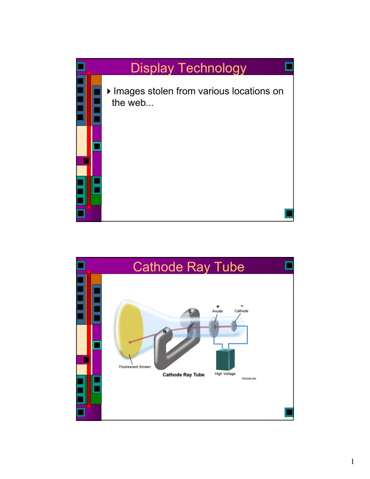
Cathode Ray Tube
SLIDE 2
2
Cathode Ray Tube Raster Scanning
SLIDE 3
3
Electron Gun Beam Steering Coils
SLIDE 4
4
Color
Shadow Mask and Aperture Grille
SLIDE 5
5
Liquid Crystal Displays Liquid Crystal Displays
SLIDE 6 6
DLP Projector LCoS
Liquid Crystal on Silicon
Put a liquid crystal between a reflective layer
SLIDE 7 7
Grating Light Valve (GLS)
lots (8000 currently) of micro ribbons that can bend slightly
Make them reflective The bends make a diffraction grating that controls how much light where Scan it with a laser for high light
4000 pixel wide frame ever 60Hz
Grating Light Valve (GLS)
SLIDE 8
8
Digistar 3 Dome Projector VGA
Stands for Video Graphics Array A standard defined by IBM back in 1987
640 x 480 pixels Now superseded by much higher resolution standards...
Also means a specific analog connector
15-pin D-subminiature VGA connector
SLIDE 9 9
VGA Connector
15: Monitor ID 3 in
10: Sync return (ground) 5: Ground 14: Vertical Sync 9: Unused 4: Unused 13: Horizontal Sync 8: Blue return (ground) 3: Blue out 12: Monitor ID 1 in
7: Green return (ground) 2: Green out 11: Monitor ID 0 in 6: Red return (ground) 1: Red out
Raster Scanning
SLIDE 10 10
VGA Timing
Horizonal Dots 640 Vertical Scan Lines 480
A (μs) 31.77 Scanline time B (μs) 3.77 Sync pulse length C (μs) 1.89 Back porch D (μs) 25.17 Active video time E (μs) 0.94 Front porch
______________________ ________ ________| VIDEO |________| VIDEO (next line) |-C-|----------D-----------|-E-| __ ______________________________ ___________ |_| |_| |B| |---------------A----------------|
60Hz vertical frequency
VGA Timing
Horizonal Dots 640 Vertical Scan Lines 480
A (μs) 31.77 Scanline time B (μs) 3.77 Sync pulse length C (μs) 1.89 Back porch D (μs) 25.17 Active video time E (μs) 0.94 Front porch
______________________ ________ ________| VIDEO |________| VIDEO (next line) |-C-|----------D-----------|-E-| __ ______________________________ ___________ |_| |_| |B| |---------------A----------------|
60Hz vertical frequency 25.17/640 = 39.33ns/pixel = 25.4MHz pixel clock
SLIDE 11 11
VGA Timing
Horizonal Dots 640 Vertical Scan Lines 480
Vertical Frequency 60Hz O (ms) 16.68 Total frame time P (ms) 0.06 Sync pulse length Q (ms) 1.02 Back porch R (ms) 15.25 Active video time S (ms) 0.35 Front porch
______________________ ________ ________| VIDEO |________| VIDEO (next frame) |-Q-|----------R-----------|-S-| __ ______________________________ ___________ |_| |_| |P| |---------------O----------------|
Relaxed VGA Timing
This all sounds pretty strict and exact... It’s not really... The only things a VGA monitor really cares about are:
Hsync Vsync Actually, all it cares about is the falling edge
The beam will retrace whenever you tell it to It’s up to you to make sure that the video signal is 0v when you are not painting (i.e. retracing)
SLIDE 12 12
Relaxed VGA Timing
Horizonal Dots 128 Vertical Scan Lines ?
A (μs) 30.0 Scanline time B (μs) 2.0 Sync pulse length C (μs) 10.7 Back porch D (μs) 12.8 Active video time E (μs) 4.50 Front porch
______________________ ________ ________| VIDEO |________| VIDEO (next line) |-C-|----------D-----------|-E-| __ ______________________________ ___________ |_| |_| |B| |---------------A----------------|
60Hz vertical frequency 12.8/128 = 100ns/pixel = 10 MHz pixel clock
VGA Timing
Horizonal Dots 128 Vertical Scan Lines 255
Vertical Frequency 60Hz O (ms) 16.68 Total frame time P (ms) 0.09 Sync pulse length (3x30μs) Q (ms) 4.86 Back porch R (ms) 7.65 Active video time S (ms) 4.08 Front porch
______________________ ________ ________| VIDEO |________| VIDEO (next frame) |-Q-|----------R-----------|-S-| __ ______________________________ ___________ |_| |_| |P| |---------------O----------------|
SLIDE 13 13
VGA Voltage Levels
Voltages on R, G, and B determine the color
Analog range from 0v (off) to +0.7v (on) But, our pads produce 0-5v outputs!
VGA Voltage Levels
Voltages on R, G, and B determine the color
Analog range from 0v (off) to +0.7v (on) But, our pads produce 0-5v outputs! For B&W output, just tie RGB together and let 0v=black and 5v=white
- verdrives the input amps, but won’t really hurt
anything
For color you can drive R, G, B separately
Of course, this is only 8 colors (including black and white) Requires storing three bits at each pixel location
SLIDE 14
14
More colors
More colors means more bits stored per pixel Also means D/A conversion to 0 to 0.7v range
More Colors (Xess)
SLIDE 15
15
What to Display?
You need data to display on the screen...
Brute force: put it all in a giant ram that has the same resolution as your screen and just walk through the RAM as you paint the screen More clever: Fill a row buffer with data for a scan line Multi-level: Fill a (smaller) row buffer with pointers to glyphs that are stored in another RAM/ROM
Just keep track of where the beam is and where your data is...
CharROM
SLIDE 16
16
CharROM Two Lines of Text
16 characters/line x 8 pixels/char = 128pixels 6 bits to address a character
A[4:3] = row of CharRom R[2:0] = column of CharRom A[2:0] = row of character
SLIDE 17
17
RAM/ROM Generator
Designed by Allen Tanner 4 years ago as his class project...
makemem
Simple SRAM and ROM arrays
ROM vs. Verilog
SLIDE 18
18
ROM vs. Verilog ROM vs. Verilog
SLIDE 19
19
ROM vs. Verilog ROM vs. Verilog
SLIDE 20
20
ROM vs. Verilog ROM vs. Verilog
SLIDE 21 21
makemem Limits
Number of rows is limited to 64 by address decoder design
Columns are not restricted
For ROM you can add a tristate bus at the output which ia another level of decoding
width must be an even number
SRAM has single, dual, and triple port
makemem
102 vladimir:~> java -cp /uusoc/facility/cad_common/local/Cadence/lib/mem/j makemem -h makemem v2.2 Nov 8, 2004 Allen Tanner University of Utah CS6710 Enter the following: java makemem choice options Where: choice selects the creation of either ROM or SRAM. for ROM enter:-r rname : rname.rom is the file name. : for SRAM enter:-s r c : Version 1 SRAM single port. for SRAM enter:-s1 r c : Version 2 SRAM single port. for SRAM enter:-s2 r c : Version 2 SRAM dual port. for SRAM enter:-s3 r c : Version 2 SRAM triple port. : r is the number of rows (decimal). : c is the number of columns (decimal). : :-h -H : help (no processing occurs when help is requested). :-f fname : output file name. Used with .cif, .v & .il files. :-n sname rname : sname for array top cell name. : : rname for ROM (only) dockable ROM array top cell name :-t n : use tristate buffers on the outputs of ROM. :-q : output hello.txt file to find the working file directory. 103 vladimir:~>