Direct Current Electricity 14-1 Equivalent Units A = W/V = N/T m - - PowerPoint PPT Presentation

direct current electricity 14 1
SMART_READER_LITE
LIVE PREVIEW

Direct Current Electricity 14-1 Equivalent Units A = W/V = N/T m - - PowerPoint PPT Presentation

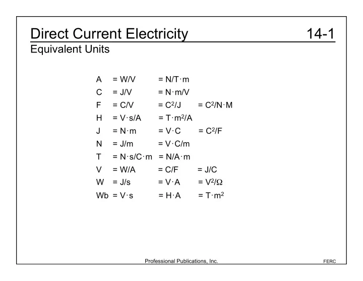
Direct Current Electricity 14-1 Equivalent Units A = W/V = N/T m C = J/V = N m/V F = C/V = C 2 /J = C 2 /N M H = V s/A = T m 2 /A J = N m = V C = C 2 /F N = J/m = V C/m T = N s/C m = N/A m V


slide-1
SLIDE 1

Professional Publications, Inc.

FERC

14-1 Direct Current Electricity

Equivalent Units

A = W/V = N/T • m C = J/V = N • m/V F = C/V = C2/J = C2/N • M H = V • s/A = T • m2/A J = N • m = V • C = C2/F N = J/m = V • C/m T = N • s/C • m = N/A • m V = W/A = C/F = J/C W = J/s = V • A = V2/Ω Wb = V • s = H • A = T • m2

slide-2
SLIDE 2

Professional Publications, Inc.

FERC

14-2 Direct Current Electricity

Basic Complex Algebra

Review FERM Ch. 43 and Mathematics Lesson 1.

slide-3
SLIDE 3

Professional Publications, Inc.

FERC

14-3a Direct Current Electricity

Electrostatics

Charges 1 Coulomb (C) = charge on 6.24 × 10¹⁸ electrons Charge on 1 e- = 1.6022 × 10⁻¹⁹ C (the inverse of 1 Coulomb) Force on Charged Object

  • General case:
  • Specific for 2 point charges:

– a is a unit vector pointing from point charge 1 to point charge 2.

slide-4
SLIDE 4

Professional Publications, Inc.

FERC

14-3b Direct Current Electricity

Electrostatics

Permittivity NOTE: On the FE exam, assume the permittivity is ε0 = 8.85 × 10⁻¹² F/m unless another value is provided. r = = actual vacuum = r0

slide-5
SLIDE 5

Professional Publications, Inc.

FERC

14-3c Direct Current Electricity

Electrostatics

Electric Field Intensity

  • Due to a point charge Q1:
  • For a line charge ρL:

– a is a unit vector normal to the line.

  • For a sheet charge ρs:

– a is a unit vector normal to the sheet charge.

slide-6
SLIDE 6

Professional Publications, Inc.

FERC

14-3d Direct Current Electricity

Electrostatics

Example (FEIM): A point charge of 0.001 C is placed 10 m from a sheet charge of –0.001 C/m2, and a 10 m diameter sphere of charge 0.001 C is placed half-way in between on a straight line, all in a vacuum. What is the force on the point charge? F = F

sheet +F sphere = Qpoint Esheet +Esphere

( )

F = Qpoint sheet 2 + Qsphere 4r

2

  • =

0.001C 8.8510

12 F

m

  • 0.001 C

m

2

2 + 0.001C 4(5 m)

2

  • = 5.6110

4 N

slide-7
SLIDE 7

Professional Publications, Inc.

FERC

14-3e1 Direct Current Electricity

Electrostatics

Electric Flux – Gauss’ Law If E is constant and parallel to d S, then Qencl = EdS

S

  • = E

dS

slide-8
SLIDE 8

Professional Publications, Inc.

FERC

Work (W) done by moving a charge Q1 radially from distance r1 to r2 in an electric field:

  • For a uniform field, the work done by moving a charge Q a

distance d parallel to the uniform field:

14-3e2 Direct Current Electricity

Electrostatics

Note that Eq. 43.27 is always true, for all fields. (V may not be easy to compute.)

slide-9
SLIDE 9

Professional Publications, Inc.

FERC

14-3f Direct Current Electricity

Electrostatics

Voltage

  • A scalar quantity that describes the electrical field.
  • The field E is the gradient of the voltage, V.
  • The voltage differential between two points is the work to bring a

unit charge from one point to the other.

  • The choice of zero potential is arbitrary.
  • Electric field strength between two parallel plates:
slide-10
SLIDE 10

Professional Publications, Inc.

FERC

Example (FEIM): A source at zero potential emits electrons at negligible velocity. An open grid at 18 V is located 0.003 m from the source. At what velocity will the electrons pass through the grid? (A) 490 m/s (B) 16 000 m/s (C) 8.3 × 10⁵ m/s (D) 2.5 × 10⁶ m/s

14-3g1 Direct Current Electricity

Electrostatics

slide-11
SLIDE 11

Professional Publications, Inc.

FERC

Therefore, the answer is (D).

14-3g2 Direct Current Electricity

Electrostatics

The mass of an electron is 9.11 x 10⁻³¹ kg. The work done by the grid on an electron is equal to the change in kinetic energy of the electron and is equal to the charge on the electron times the change in voltage potential. W = 1

2 mv 2 = qV

v = 2qV m = (2)(1.602210

19 C)(18 V)

9.1110

31kg

= 2.51610

6 m/s

2.510

6 m/s

( )

slide-12
SLIDE 12

Professional Publications, Inc.

FERC

14-4 Direct Current Electricity

Current

Change in charge per unit time Current Density (ρ)

  • The density of charge moving per unit time through a volume

Volume Current Density (J)

  • The vector current density
slide-13
SLIDE 13

Professional Publications, Inc.

FERC

14-5a Direct Current Electricity

Magnetism

Magnetic field around a current-carrying wire Force on current-carrying conductor

slide-14
SLIDE 14

Professional Publications, Inc.

FERC

14-5b Direct Current Electricity

Magnetism

Example (FEIM): A magnetic field of 0.0005 T makes a 30° angle with a 1 m wire carrying 0.05 A. What is the force on the wire? (A) 1.25 × 10⁻⁵ N (B) 5.00 × 10⁻⁴ N (C) 1.25 × 10⁻³ N (D) 2.50 × 10⁻³ N Therefore, the answer is (A). F = I L B = I L B sin = (0.05 A)(1 m)(0.0005 T)(sin30°) = 1.2510

5 N

slide-15
SLIDE 15

Professional Publications, Inc.

FERC

14-6 Direct Current Electricity

Induced Voltage

Also called electromotive force (emf) For N loops:

slide-16
SLIDE 16

Professional Publications, Inc.

FERC

14-7a Direct Current Electricity

DC Circuits

Resistivity Depends on temperature: Example (FEIM): A cube with an edge length of 0.01 m has resistivity of 0.01 Ω • m. What is the resistance from one side to the opposite side? (A) 0.0001 (B) 0.001 (C) 0.1 (D) 1 Therefore, the answer is (D). R = L A = (0.01m)(0.01m) (0.01m)

2

= 1

slide-17
SLIDE 17

Professional Publications, Inc.

FERC

14-7b Direct Current Electricity

DC Circuits

Ohm’s Law Resistors in Series: Resistors in Parallel: Equivalent resistance of two resistors in parallel: Resistive Power

slide-18
SLIDE 18

Professional Publications, Inc.

FERC

14-7c Direct Current Electricity

DC Circuits

Example (FEIM): What is the resistance of the following circuit as seen from the battery? No current will flow through the two 4 Ω resistors, the two 3 Ω resistors,

  • r the 7 Ω resistor. The circuit reduces to one 6 Ω in series with two 12

Ω in parallel. R = 6 + 6 = 12

slide-19
SLIDE 19

Professional Publications, Inc.

FERC

14-7d Direct Current Electricity

DC Circuits

Kirchhoff’s Laws

  • Voltage Law (KVL)
  • Current Law (KCL)
slide-20
SLIDE 20

Professional Publications, Inc.

FERC

14-7e Direct Current Electricity

DC Circuits

Loop Current Circuit Analysis

  • 1. Select one less than the total number of loops.
  • 2. Write Kirchhoff’s voltage equation for each loop.
  • 3. Use the simultaneous equations to solve for the current you want.
slide-21
SLIDE 21

Professional Publications, Inc.

FERC

14-7f Direct Current Electricity

DC Circuits

Example (FEIM): Find the current through the 0.5 Ω resistor. The voltage sources around the left loop are equal to the voltage drops across the resistances. 20 V – 19 V = 0.25 Ω i1 + 0.4 Ω (i1 – i2) The same is true for the right loop. 19 V = 0.4 Ω (i2 – i1) + 0.5 Ω i2 Solve—two equations and two unknowns. 0.65 Ω i1 – 0.4 Ω i2 = 1 V –0.4 Ω i1 + 0.9 Ω i2 = 19 V i1 = 20 A i2 = 30 A The current through the 0.5 Ω resistor is 30 A.

slide-22
SLIDE 22

Professional Publications, Inc.

FERC

14-7g Direct Current Electricity

DC Circuits

Node Voltage Circuit Analysis

  • 1. Convert all current sources to voltage sources.
  • 2. Choose one node as reference (usually ground).
  • 3. Identify unknown voltages at other nodes compared to reference.
  • 4. Write Kirchhoff’s current equation for all unknown nodes except

reference node.

  • 5. Write all currents in terms of voltage drops.
  • 6. Write all voltage drops in terms of the node voltages.
slide-23
SLIDE 23

Professional Publications, Inc.

FERC

14-7h Direct Current Electricity

DC Circuits

Example (FEIM): Find the voltage potential at point A and the current i1. i1 + i2 = i3 50 V VA 2 + 20 V VA 4 = VA 0 10 VA = 35.3 V i1 = 50 V VA 2 = 50 V 35.3 V 2 = 7.35 A

slide-24
SLIDE 24

Professional Publications, Inc.

FERC

14-8a Direct Current Electricity

Voltage Divider

The voltage across a resistor R in a loop with total resistance Rtotal with a voltage source V is In the general case, the voltage on impedance Zi in a loop with total impedance Ztotal with a voltage source v is NOTE: Each symbol is a complex number in the general case. VR = R Rtotal V vi = Zi Ztotal

slide-25
SLIDE 25

Professional Publications, Inc.

FERC

14-8b Direct Current Electricity

Voltage Divider

Example (FEIM): What is the voltage across the 6 Ω resistor? (A) 5 V (B) 6 V (C) 8 V (D) 10 V Two 8 Ω resistors in parallel equal 4 Ω. The voltage across the 6 Ω resistor is Therefore, the answer is (B). (10 V) 6 6 + 4

  • = 6 V
slide-26
SLIDE 26

Professional Publications, Inc.

FERC

14-9a Direct Current Electricity

Current Divider

The current through a resistor R in parallel with another resistance Rparallel and a current into the node of I is: In the general case, the current through impedance Zi connected to a node in parallel with total impedance Ztotal with a current i into the node is: NOTE: Each symbol is a complex number in the general case. Procedure:

  • 1. Identify the component you want the current through.
  • 2. Simplify the circuit.
  • 3. Determine the current into the node that is connected to the

component of interest.

  • 4. Allocate current in proportion to the reciprocal of resistance.

IR = Rparallel Rtotal I (Resistance R does not appear explicitly. Rtotal is the sum of the resistances in parallel.) iZi = Zparallel Ztotal i (Ztotal is the sum of the impedances in parallel.)

slide-27
SLIDE 27

Professional Publications, Inc.

FERC

14-9b Direct Current Electricity

Current Divider

Example (FEIM): What is the current through the 6 Ω resistor? (A) 1/10 A (B) 1/3 A (C) 1/2 A (D) 1 A Simplify the circuit. i = i1 + i2 3 Ω in parallel with 6 Ω = 2 Ω 2 Ω in series with 4 Ω = 6 Ω Rparallel = 3 Ω Rtotal = 3 Ω + 6 Ω = 9 Ω i = 6 V 6 = 1 A i = (1 A) 3 3 + 6

  • = 1/3 A

Therefore, the answer is (B).

slide-28
SLIDE 28

Professional Publications, Inc.

FERC

14-10a Direct Current Electricity

Superposition Theorem

The net current/voltage is the sum of the current/voltage caused by each current/voltage source. Procedure:

  • 1. Short all voltage sources, and open all current sources, then turn
  • n only one source at a time.
  • 2. Simplify the circuit to get the current/voltage of interest.
  • 3. Repeat until all sources have been used.
  • 4. Add the results for the answer.
slide-29
SLIDE 29

Professional Publications, Inc.

FERC

14-10b Direct Current Electricity

Superposition Theorem

Example (FEIM): Determine the current through the center leg of the circuit. Short the 20 V source. I = 50V 2 = 25 A Short the 50 V source. I = 20V 4 = 5 A Itotal = 25 A +5 A = 30 A

slide-30
SLIDE 30

Professional Publications, Inc.

FERC

14-11a Direct Current Electricity

Norton Equivalent

slide-31
SLIDE 31

Professional Publications, Inc.

FERC

14-11b Direct Current Electricity

Norton Equivalent

Example (FEIM): Find the Norton equivalent current and resistance of the circuit as seen by the 10 Ω resistor. With the 10 Ω resistor open circuited, and the voltage sources shorted, the circuit is 4.0 Ω and 2.0 Ω in parallel. With the 10 Ω resistor shorted, the circuit looks just like the previous example. RN = 2

( )

4 2 + 4

  • = 1.33

IN = 30 A

slide-32
SLIDE 32

Professional Publications, Inc.

FERC

14-12a Direct Current Electricity

Thevenin Equivalent

slide-33
SLIDE 33

Professional Publications, Inc.

FERC

14-12b1 Direct Current Electricity

Thevenin Equivalent

Example (FEIM): Find the Thevenin equivalent voltage and resistance of the circuit as seen by the 10 Ω resistor. The Thevenin resistance is the same as the Norton resistance in the previous example, which is 1.3 Ω. With the 10 Ω resistor open-circuited, apply the Kirchhoff voltage law around the loop and find VTH = 40 V.

slide-34
SLIDE 34

Professional Publications, Inc.

FERC

14-12b2 Direct Current Electricity

Thevenin Equivalent

(50 V 20 V) = I(2 + 4 ) I = 5 A V = 50 V I(2 ) = 40 V = 50 V (5 A)(2 )

slide-35
SLIDE 35

Professional Publications, Inc.

FERC

14-13a Direct Current Electricity

Capacitors

Parallel Plate Capacitors

  • Capacitance in Parallel:
  • Capacitance in Series:
slide-36
SLIDE 36

Professional Publications, Inc.

FERC

14-13b Direct Current Electricity

Capacitors

Example 1 (FEIM): What is the capacitance seen by the battery? The two 2 µF capacitors in parallel are equivalent to 4 µF. The 1 µF capacitor in series with the equivalent 4 µF capacitance will add as resistors in parallel. C = C1C2 C1 +C2 = (1µF)(1µF) 1µF+ 4 µF = 4/5 µF

slide-37
SLIDE 37

Professional Publications, Inc.

FERC

14-13c Direct Current Electricity

Capacitors

Example 2 (FEIM): A 10 µF capacitor has been connected to a potential source of 150 V. The energy stored in the capacitor in 10 time constants is most nearly (A) 1.0 x 10⁻⁷ J (B) 9.0 x 10⁻³ J (C) 1.1 x 10⁻¹ J (D) 9.0 x 101 J Therefore, the answer is (C). Energy = (1010

6 F)(150 V) 2

2 = 0.11 J (1.110

1 J)

slide-38
SLIDE 38

Professional Publications, Inc.

FERC

14-14a Direct Current Electricity

Inductors

  • Inductance in Series:
  • Inductance in Parallel:
slide-39
SLIDE 39

Professional Publications, Inc.

FERC

14-14b Direct Current Electricity

Inductors

Example (FEIM): Find the inductance as seen from the battery. The two 2 mH inductors in parallel will add as resistors in parallel. The 1 mH inductor in series with the equivalent 1 mH inductance will combine for 2 mH total inductance. L = L1L2 L1 +L2 = (2 mH)(2 mH) 2 mH+ 2 mH = 1 mH

slide-40
SLIDE 40

Professional Publications, Inc.

FERC

14-15a Direct Current Electricity

RC Transients

slide-41
SLIDE 41

Professional Publications, Inc.

FERC

14-15b1 Direct Current Electricity

RC Transients

Example (FEIM): At t = 0, the capacitor is discharged, and the switch is moved from A to B. At t = 6 s, the switch is moved to C. (a) What is the capacitor voltage at t = 6 s? (b) What is the current at t = 10 s? (c) When (after 6 s) is the voltage across the capacitor equal to 10 V?

slide-42
SLIDE 42

Professional Publications, Inc.

FERC

14-15b2 Direct Current Electricity

RC Transients

(a) From time = 0 to 6 s, Vc (0) = 0 V = 50 V RC = (51 x 103 Ω)(100 x 10-6 F) = 5.1 s So 34.58 V is the peak voltage the capacitor reaches before it starts to discharge. c(6 s) = 0e

6 s 5.1 s +50 V 1 e 6 s 5.1 s

  • = 34.58 V
slide-43
SLIDE 43

Professional Publications, Inc.

FERC

14-15b3 Direct Current Electricity

RC Transients

(b) From time = 6 s on, Vc (6 s) = 34.58 V V = 0 V RC = (10 x 103 Ω)(100 x 10-6 F) = 1 s i(10 s) = 0 34.58 V 1010

3

  • e

10 s6 s 1

= 6.310

5 A

(c) Take the natural logarithm of both sides of the equation vc(t) = 34.58 Ve

t6 s 1 s +0 1 e t6 s 1 s

  • = 10 V

ln34.58 V e

(t6 s) = ln10

lne

(t6 s) +ln34.58 V = ln10

(t 6 s) = ln10 ln34.58 V t 6 s = 1.24 s t = 7.24 s

slide-44
SLIDE 44

Professional Publications, Inc.

FERC

14-16a Direct Current Electricity

RL Transients

slide-45
SLIDE 45

Professional Publications, Inc.

FERC

14-16b Direct Current Electricity

RL Transients

Example (FEIM): Find the voltage at point A at the instant the switch is closed. The switch has been open for a long time, and there is no initial current in the inductor. Therefore, the answer is (D). i(0) = 0 V = 12 V, so at t = 0 L(0

+) = 0Re 0 + 12 V

( )e

0 = 12 V

(A) 0 V (B) 1 V (C) 3 V (D) 12 V

slide-46
SLIDE 46

Professional Publications, Inc.

FERC

14-17 Direct Current Electricity

Transducers

A transducer is any device used to convert a physical phenomenon into an electrical signal (e.g., microphone, thermocouple, and voltmeter). Characteristics of measurement design:

  • Sensitivity
  • Linearity
  • Accuracy
  • Precision
  • Stability
slide-47
SLIDE 47

Professional Publications, Inc.

FERC

14-18a Direct Current Electricity

Resistance Temperature Detectors (RTDs)

Make use of changes in their resistance to determine the changes in temperature. Example (FEIM): A resistance temperature detector (RTD) that is not perfectly linear is used for a temperature measurement. The temperature coefficient is 3.900 × 10⁻³ºC–1, the reference temperature is 0ºC, and the reference resistance is 500.0 Ω. The resistance measured when the actual temperature is 400ºC is 1247 Ω. Determine the error in the temperature measurement.

slide-48
SLIDE 48

Professional Publications, Inc.

FERC

14-18b Direct Current Electricity

Resistance Temperature Detectors (RTDs)

If the RTD was perfectly linear the resistance would be given by However, the temperature that the RTD indicates is not the actual temperature of 400ºC, so rearranging the RTD equation to solve for the temperature that the RTD indicates yields RT = R0 1+ (T T0)

( )

T = RT R0 + R0T0 R0 = 1247 500.0 +(3.90010

3 °C 1)(500°C)(0°C)

(3.90010

3 °C 1)(500°)

= 383.1°C The error in the measurement is: Error = 383.1ºC – 400ºC = –16.9ºC

slide-49
SLIDE 49

Professional Publications, Inc.

FERC

14-19a1 Direct Current Electricity

Strain Gages

Metal or semiconductor foils that change resistance linearly with the strain. Example (FEIM): A strain gage is measured to determine the gage factor. A strain gage with an initial resistance of 200.00 Ω and final resistance of 199.79 Ω when subjected to a strain that causes the gage to compress to 0.9994

  • cm. The initial length of the gage was 1.0000 cm. What is the gage

factor? (A) 0.15 (B) 0.42 (C) 1.8 (D) 4.0

slide-50
SLIDE 50

Professional Publications, Inc.

FERC

14-19a2 Direct Current Electricity

Strain Gages

Therefore, the answer is (C). GF = R R L L = 199.79 200.00 200.00 0.9994 cm1.0000 cm 1.0000 cm = 1.75

slide-51
SLIDE 51

Professional Publications, Inc.

FERC

14-20a Direct Current Electricity

Wheatstone Bridges

Balanced: Quarter-bridge:

slide-52
SLIDE 52

Professional Publications, Inc.

FERC

14-20b Direct Current Electricity

Wheatstone Bridges

Example (FEIM): There are three high-precision resistors known to be 10.00 kΩ in a quarter bridge circuit. R1 is a sensor with a small resistance difference from 10 kΩ. Find the resistance if Vin = 5.00 V and Vo = 0.03 V. For the strain gage quarter-bridge circuit, ΔR can be substituted. R = 4RVo Vin = (4)(10.00 k)(0.03 V) 5.00 V = 0.24 k Vo = 1 4(GF)Vin R1 = 10.00 k+0.24 = 10.24 k

slide-53
SLIDE 53

Professional Publications, Inc.

FERC

14-21a Direct Current Electricity

Sampling

Sampling Rate or Frequency: Shannon’s Sampling Theorem Determines the sampling rate to reproduce accurately in the discrete time system. Nyquist Rate: Reproducible Sampling: fs > fn [reproducible sampling] (where fI is the frequency of interest)

slide-54
SLIDE 54

Professional Publications, Inc.

FERC

14-21b1 Direct Current Electricity

Sampling

Example (FEIM): An analog signal is to be sampled at 0.03 µs intervals. What is most nearly the highest frequency that can be accurately reproduced? (A) 4.0 × 10⁶ Hz (B) 12 × 106 Hz (C) 16 × 106 Hz (D) 18 × 106 Hz The sampling frequency is fs = 1 t = 1 0.0310

6

= 3310

6 Hz

slide-55
SLIDE 55

Professional Publications, Inc.

FERC

14-21b2 Direct Current Electricity

Sampling

The sampling frequency must be greater than the Nyquist rate for accurate reproduction. The greatest frequency that can be reproduced at this sampling rate is Therefore, the answer is (C). fs > 2fN fN < fs 2 = 3310

6 Hz

2 = 16.710

6 Hz (1610 6 Hz)

slide-56
SLIDE 56

Professional Publications, Inc.

FERC

14-22a Direct Current Electricity

Analog-to-Digital Conversion

Voltage Resolution The range from a high voltage, VH, and a low voltage, VL, is divided up into the 2n ranges. For example, if all the bits are “1” then the analog value is somewhere between VH and VH – εV. To calculate the analog value from the digital value use

slide-57
SLIDE 57

Professional Publications, Inc.

FERC

14-22b Direct Current Electricity

Analog-to-Digital Conversion

Example (FEIM): A 16 bit analog-to-digital conversion has a resolution of 1.52588 × 10⁻⁴ V and the lowest voltage measured has half the magnitude of the highest voltage. Both the high and low voltages are positive. Determine the highest voltage. The problem statement also says that Since VH and VL are positive, this equation becomes VH = 2VL Substituting into the first equation 2VL – VL = 10 V VL = 10 V VH = 20 V VH VL = 2

nv

= (2)

16(1.5258810 4 V)

= 10.0 V VH = 2VL

slide-58
SLIDE 58

Professional Publications, Inc.

FERC

14-23a Direct Current Electricity

Measurement Uncertainty

Kline-McClintock Equation: A method for estimating the uncertainty in a function that depends on more than one measurement.

slide-59
SLIDE 59

Professional Publications, Inc.

FERC

14-23b1 Direct Current Electricity

Measurement Uncertainty

Example (FEIM): A function is given by Find the measurement uncertainty at (1, 2) if the uncertainty in the variables is ±0.01 and ±0.03 respectively. At the point (1, 2) the partial derivatives are R = 5x1 3x2

2.

R x2 = 6x2 R x1 = 5 R x2 (1,2) = (6)(2) = 12 R x1 (1,2) = 5 wR = w1 R x1 (1,2)

  • 2

+ w2 R x2 (1,2)

  • 2

= (0.01 )(5)

( )

2 + (0.03)(12)

( )

2

= 0.36

slide-60
SLIDE 60

Professional Publications, Inc.

FERC

14-23b2 Direct Current Electricity

Measurement Uncertainty

If the function R is the sum of the measurements, R = x1 + x2 + x3 + … + xn, then the Kline-McClintock method reduces to This is called the root sum square (RSS) value. If the function R is the sum of the measurements times constants, R = a1x1 + a2x2 + a3x3 + … + anxn, then the Kline-McClintock method reduces to This is called a weighted RSS value. wR = w1

2 +w2 2 +L+wn 2

wR = a1

2w1 2 +a2 2w2 2 +L+an 2wn 2