
SLIDE 1
DESERT SOUTHWEST REGION
10-YEAR PLAN
INTERTIE & PARKER DAVIS PROJECT
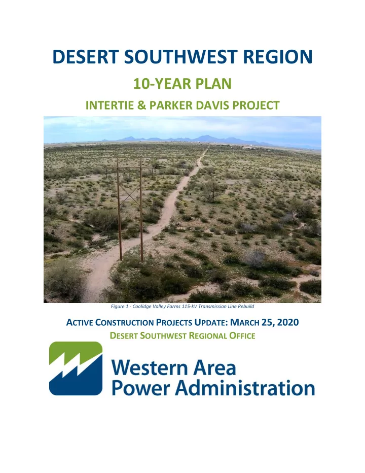
Figure 1 - Coolidge Valley Farms 115-kV Transmission Line Rebuild
DESERT SOUTHWEST REGION 10-YEAR PLAN INTERTIE & PARKER DAVIS - - PDF document
DESERT SOUTHWEST REGION 10-YEAR PLAN INTERTIE & PARKER DAVIS PROJECT Figure 1 - Coolidge Valley Farms 115-kV Transmission Line Rebuild A CTIVE C ONSTRUCTION P ROJECTS U PDATE : M ARCH 25, 2020 D ESERT S OUTHWEST R EGIONAL O FFICE Table of
Figure 1 - Coolidge Valley Farms 115-kV Transmission Line Rebuild
2 Desert Southwest Region |wapa.gov
Table of Contents
...................................................................................................... 6 4.1 What Is The 10-Year Plan Pivot?........................................................................................................ 6 4.2 Why Do We Need to Pivot? ............................................................................................................... 6 4.3 Customer Benefits ............................................................................................................................. 6
...................................................................................... 7 5.1 Coolidge-Valley Farms 115-kV Rebuild .............................................................................................. 7 5.2 Liberty Series Capacitor Bank Replacement .................................................................................... 10 5.3 Kofa-Dome Tap 161-kV Rebuild....................................................................................................... 13 5.4 Dome Tap-Gila 161-kV Rebuild ........................................................................................................ 16 5.5 Gila-Wellton Mohawk Interstate 8 Crossing 161-kV Rebuild .......................................................... 20 5.6 Gila Substation 161-kV Rebuild ....................................................................................................... 23 5.7 Bouse-Kofa 161-kV Rebuild ............................................................................................................. 26
................................................................................................................... 30 Bouse Upgrade Alternative Investigation ................................................................................................... 30
7.1 Parker-Blythe 161-kV Rebuild Study ............................................................................................... 36 7.2 Crossman Peak New Microwave Facility ......................................................................................... 38 7.3 Gila Substation 69-kV Rebuild Study ............................................................................................... 42 7.4 Blythe-Headgate Rock Rebuild Study .............................................................................................. 45
3 Desert Southwest Region |wapa.gov
Wednesday, March 25, 2020 | 10 a.m. to 12 p.m. Mountain Standard Time (Arizona) WEBEX VIDEO CONFERENCING AND CALL-IN NUMBER:
To access the Webex please visit WAPA’s website. You can find a link below. https://www.wapa.gov/regions/DSW/Pages/10-year-capital-program.aspx Scroll to the customer meeting and click “Join”, then follow the on-screen prompts OBJECTIVES Provide status updates on all active construction projects Provide status updates on seed project Provide status updates on Analysis of Alternatives Studies Solicit customer input on new study alternatives AGENDA Presenter Time Allotment
Jack Murray 5 min
Tony Guinane 5 min
Roger Wright 5 min
Roger Wright 5 min
Mike Garcia 5 min
Tony Gagajewski 5 min
Tony Gagajewski 5 min f. Gila Substation 161-kV Rebuild Tony Gagajewski 5 min
Tony Gagajewski 5 min
Tony Gagajewski 10 min
Tony Guinane 20 min
Tony Guinane 5 min
4 Desert Southwest Region |wapa.gov
ACSR……………………….…………………………………….…………..………..ALUMINUM CONDUCTOR STEEL REINFORCED ACSS………………………………………….………………….………………….....ALUMINUM CONDUCTOR STEEL SUPPORTED AOA…………………………….……………………………………………….……………………..ANALYSIS OF ALTERNATIVES STUDY DSW…………………………………………………………………………………………………………….DESERT SOUTHWEST REGION IGE………………………………………………………………………………………………INDEPENDENT GOVERNMENT ESTIMATE KCMIL…………………………………………….………….………………………………………………...THOUSANDS CIRCULAR MILS MVA……………………………………………………………………………………………………………………………….MEGA VOLT AMP OGW………………………………………………………………………………………………………..………OVERHEAD GROUND WIRE OPGW………………………………………………………………………………………….…….OPTICAL OVERHEAD GROUND WIRE ROW…………………………………………………….……………….………………….……….……………………………..RIGHT-OF-WAY TYP…………………………………………………………………………………………………………………………….……….10-YEAR PLAN WAPA………………………………………….…………………………………………..WESTERN AREA POWER ADMINISTRATION
5 Desert Southwest Region |wapa.gov
Figure 1 - Coolidge Valley Farms 115-kV Transmission Line Rebuild ............................................................ 1 Figure 2- WAPA-DSW Transmission Line System .......................................................................................... 7 Figure 3 - Aerial View of Coolidge-Valley Farms 115-kV Transmission Line ................................................. 8 Figure 4 - Aerial View of Liberty Substation ................................................................................................ 11 Figure 5 - New Liberty Series Capacitor Bank ............................................................................................. 11 Figure 6 - Existing Kofa-Dome Tap 161-kV Transmission Line .................................................................... 14 Figure 7 - Aerial Patrol Photo Showing Limited Right-of-Way Access ........................................................ 15 Figure 8 - Aerial View of Gila-Dome Tap 161-kV Structure Replacement .................................................. 17 Figure 9 - Aerial View of Gila-Dome Tap 161-kV through Agricultural Lands ............................................. 17 Figure 10 - New Take-off Structure at Dome Tap ....................................................................................... 18 Figure 11 - Gila-Wellton Mohawk 161-kV Rebuild ...................................................................................... 21 Figure 12 - Arial view of the New Gila 161-kV Substation .......................................................................... 24 Figure 13 - Erosion Control Adjacent to the New Gila 161-kV Substation.................................................. 25 Figure 14 - Bouse-Kofa 161-kV Alignment .................................................................................................. 27 Figure 15 - Bouse-Kofa 161-kV Transmission Line ...................................................................................... 28 Figure 16 - Current Parker-Headgate Rock & Parker Bouse Transmission Line Configuration .................. 31 Figure 17 – Alternative Bouse Upgrade Configuration ............................................................................... 31 Figure 18 - Existing South of Parker System Configuration ........................................................................ 32 Figure 19 - Proposed Bouse Upgrade Configuration South of Parker ........................................................ 32 Figure 20 - Wilderness Areas Discovered During Seed Funding Phase....................................................... 34 Figure 21 - Location of New Crossman Peak Microwave Site (Yellow Dot) ................................................ 39 Figure 22 - View Looking up Crossman Peak Microwave Facility ............................................................... 40 Figure 23 - Existing Non-WAPA Structure on Crossman Peak .................................................................... 41 Figure 24 - Gila 69-kV Substation ................................................................................................................ 43 Figure 25- Gila 69kV/34.5kV Transformer .................................................................................................. 44 Figure 26 - Decommissioned Oil Storage Building Adjacent ....................................................................... 44 Figure 27 - Existing Wood H-Frame Structures on Blythe-Headgate Rock Transmission Line ................... 46 Figure 28 – Existing Steel H-Frame Structures on Blythe-Headgate Rock Transmission Line .................... 46
6 Desert Southwest Region |wapa.gov
4.1 What Is The 10-Year Plan Pivot?
The pivot is a strategic one-time shift in the 10-Year Plan process that requires simultaneous approval of multiple upcoming capital improvement projects. The pivot spans multiple 10-Year Plan cycles and may incorporate simultaneous prepayment funding approvals across multiple fiscal years. The pivot will conclude with the 10-Year Plan in alignment with the Government’s Budget Formulation Process such that prepayment funding will be approved two years in advance of the start of new projects.
4.2 Why Do We Need to Pivot?
The Federal Government Budget Formulation process begins two fiscal years prior to the execution year (current year). Historically, conducting the prepayment funding vote in the same year as the proposed construction start creates inconsistencies and unpredictability in the execution of WAPA’s annual budget, which is formulated two years prior. The result is last minute modifications to resource allocations in order to compensate for budgetary swings. Historically the two year grace period between budget formulation and prepayment funding approval was prone to changes and fluctuation due to competing priorities and uncertainty of approved prepayment funding. By aligning the customer prepayment vote with the budget formulation process, WAPA can improve accuracy, consistency, and predictability in its budget formulation and execution. Aligning capital planning with budget formulation is imperative to the success
4.3 Customer Benefits
As a result of a successful pivot, the customers will gain additional input into Analysis of Alternatives (AOA) study prioritization, planning, and results. Previously the AOAs were being performed concurrent with budget formulation processes, such that opportunities for customer input/engagement were limited. The strategic plan to pivot will provide customers with capital planning information in advance of budget formulation, therefore allowing sufficient time for WAPA to develop diverse, viable, and economical investment alternatives for customer consideration.
7 Desert Southwest Region |wapa.gov
5.1 Coolidge-Valley Farms 115-kV Rebuild
Power System: Parker-Davis Project Project Location =
Figure 2- WAPA-DSW Transmission Line System
Project Background Coolidge to Valley Farms (COL-VAF) is a single circuit, 6.1-mile, 115-kV transmission line segment of the Coolidge to Oracle (COL-ORA) 45-mile transmission line. The structures being replaced are mainly wood H-frame structures with a 4/0 copper conductor and two overhead ground wires (OGW). The rebuild effort included the replacement in-kind of existing deteriorated wood pole structures. Replacement of the new wood poles were located in the same location as the existing poles to avoid environmental and access concerns. Transmission Work Substation Work Communication
8 Desert Southwest Region |wapa.gov The existing copper conductor rated at 88 MVA has been upgraded to Cardinal 954-KCMIL aluminum conductor steal reinforced (ACSR) conductor rated at approximately 180-MVA with the addition of one new overhead optical ground wire (OPGW) and one standard OGW.
Figure 3 - Aerial View of Coolidge-Valley Farms 115-kV Transmission Line
The scope also includes minor substation work at the terminal ends of the line to upgrade or replace equipment required to achieve the increased capacity on the conductor. This includes but is not limited to jumper replacements. Work at each substation also includes communication upgrades in the control rooms to land and integrate the new OPGW. Project Scope Highlights Replace 6.1 miles of 4/0 copper conductor with 954-KCMIL ACSR conductor Replace all insulators and hardware Install one new OGW and OPGW to improve communications Replace wood structures in-kind where replacements are required or to support the new conductor Upgrade deteriorated cross arms assemblies with glue-laminated (glulam) cross-arms Install new steel angle, 4” x 3 ½” x 5/16” x 14’-6” long (pole-to-pole ties) between H-frame structures to support new OPGW and OGW Clear ROW access roads and pads as required for construction and maintenance Correct all NESC/NERC clearance violations Project Updates The project is in the final stages of construction with the outage concluding on May 30, 2020. As the project advances on schedule, WAPA has forecasted that the project will be executed under budget as a result of the construction contract being awarded below the independent government estimate (IGE). As a result, in December of 2019 WAPA transferred ~$807,000 in prepayment funds to the active Gila Substation 161-kV Rebuild Project.
9 Desert Southwest Region |wapa.gov Project Financial Summary Project Milestones
10 Desert Southwest Region |wapa.gov
5.2 Liberty Series Capacitor Bank Replacement
Power System: Intertie Project Project Location = Project Background The Liberty 345-kV Series Capacitor Bank Replacement project was initiated in late 2016. The project involved the installation of a new 345-kV series capacitor bank to replace the existing, in-service, Westinghouse capacitor bank. The new unit is rated at 345-kV, 110-MVar, and 850 Amps (508 MVA). The replaced capacitor bank was originally commissioned in 1969 and had degraded significantly. The series capacitor bank is made up of capacitor cans, a control system, air compressor, air dryer, air piping system, inserting circuit breaker, relaying, surge arrestors and reactors. Project Scope Highlights Replace existing, in service, 345-kV series capacitor bank New series capacitor bank installed adjacent to the old unit The old capacitor bank unit removed and foundations left in place Transmission Work Substation Work Communication
11 Desert Southwest Region |wapa.gov
Figure 4 - Aerial View of Liberty Substation
Project Updates The construction contractor re-mobilized in September 2019 to continue work under a three month planned outage to complete the field work in early 2020. Currently the project is on schedule and under
awarded below the independent government estimate (IGE). As a result, in December of 2019 WAPA transferred ~$537,000 in prepayment funds to the active Gila Substation 161-kV Rebuild Project.
Figure 5 - New Liberty Series Capacitor Bank
12 Desert Southwest Region |wapa.gov Project Financial Summary Project Milestones
13 Desert Southwest Region |wapa.gov
5.3 Kofa-Dome Tap 161-kV Rebuild
Power System: Parker-Davis Project Project Location = Project Background Kofa (KOF) to Dome Tap (DME) is a single-circuit, 7.3-mile, 161-kV transmission line segment along the Parker-Gila 161-kV line built in 1943. The KOF-DME Transmission Line is located in western Arizona running south from the Kofa substation to Dome Tap. The line was originally constructed with 300-KCMIL hollow-core-copper conductor. Most of the wood H-Frame structures have been replaced with light-duty steel H-Frame structures, and only seven wood structures remain in service. WAPA will replace existing copper conductor with 336.4-KCMIL ACSS conductor, replace one steel
H-frame structures to replace the seven wood structures remaining in the line segment. Transmission Work Substation Work Communication
14 Desert Southwest Region |wapa.gov WAPA will also install new light-duty steel H-frame steel structures as needed to correct phase-to-ground clearance issues not corrected by stringing new ACSS conductor. Lastly, WAPA will repair and improve access roads as needed.
Figure 6 - Existing Kofa-Dome Tap 161-kV Transmission Line
Project Scope Highlights Replace 7.3 miles of 300-KCMIL copper conductor with 336.4-KCMIL ACSS conductor Replace remaining wood pole structures with light-duty steel structures Replace one steel OGW in-kind Upgrade one steel OGW to OPGW to improve communications Replace all insulators and hardware Correct all phase-to-ground clearance issues Replace take-off structures inside Dome-Tap substation Clear ROW access roads and pads as required for construction and maintenance
15 Desert Southwest Region |wapa.gov
Figure 7 - Aerial Patrol Photo Showing Limited Right-of-Way Access
Project Updates Project is proceeding on time and on budget with the construction contract awarded in February 2020. All government furnished materials have been ordered and are scheduled to arrive onsite by October
Project Financial Summary Project Milestones
16 Desert Southwest Region |wapa.gov
5.4 Dome Tap-Gila 161-kV Rebuild
Power System: Parker-Davis Project Project Location = Project Background Gila (GLA) to Dome Tap (DME) is a single circuit, 7.6 mile, 161-kV transmission line segment of the overall Parker-Gila 161-kV line built in 1943. The line runs through agricultural, residential, and commercial property as well as hills and flat low desert terrain. The northern line section crosses Highway 95, the Union Pacific Railroad, and the Wellton Mohawk Canal. Originally constructed with wood H-frame structures, maintenance activities have replaced all but 16 of the structures with light-duty steel. Ten phase-to-ground clearance violations have been identified along the 300-KCMIL hollow core copper conductor. Transmission Work Substation Work Communication
17 Desert Southwest Region |wapa.gov
Figure 8 - Aerial View of Gila-Dome Tap 161-kV Structure Replacement Figure 9 - Aerial View of Gila-Dome Tap 161-kV through Agricultural Lands
18 Desert Southwest Region |wapa.gov
Figure 10 - New Take-off Structure at Dome Tap
Project Scope Highlights Replace 7.6 miles of 300-KCMIL hollow core copper conductors with 336.4-KCMIL ACSS conductors Install light-duty steel H-frame structures, replacing the remaining 16 wood structures on the line Three Light-duty steel structures will be replaced with new taller structures to rectify phase-to-ground clearance issues Replace one steel OGW in-kind Upgrade one steel OGW to OPGW to improve communications Replace all insulators and hardware Clear ROW access roads and pads Replace two take-off structures inside Dome-Tap substation
19 Desert Southwest Region |wapa.gov Project Updates Project construction kicked off in October 2019 and is proceeding on time and on budget. The current in- service date is projected for the middle of 2020. Project Financial Summary Project Milestones
20 Desert Southwest Region |wapa.gov
5.5 Gila-Wellton Mohawk Interstate 8 Crossing 161-kV Rebuild
Power System: Parker-Davis Project Project Location = Project Background The Gila-Wellton Mohawk (GLA-WML) 161-kV transmission line rebuild project was initiated in late 2016 as part of the Seed Funding Pilot Program. WAPA kicked off the project and began design work to rebuild 2.8 miles of the original wood structures along the GLA-WML transmission line. The line was originally erected in 1956 and the structures were well beyond the recommended lifespan and rehabilitation efforts were no longer viable. Many of the poles displayed visual symptoms of advanced external shell rot, along with weathering and large cracks. Transmission Work Substation Work Communication
21 Desert Southwest Region |wapa.gov During 2017, a majority of the GLA-WML structures were replaced by WAPA maintenance personnel; however, a stretch of transmission line that traverses rugged, mountainous terrain was not replaced. This was due in part because many of the structures had no existing access roads and those that did, required significant roadwork for vehicular travel. In conjunction with the rebuild effort, WAPA reestablished access roads where economically feasible to reduce the potential for helicopter only access. In addition,
Figure 11 - Gila-Wellton Mohawk 161-kV Rebuild
Project Scope Highlights Rebuild 2.8 miles of single circuit 161-kV transmission line through mountainous terrain Replace original wood structures with steel mono-poles with micro-pile foundations Install OPGW for communication Replace all insulators and hardware Project Updates Project was completed in the second quarter of 2019, ahead of schedule and on budget. Although WAPA is new to the use of micro-pile foundations, their installation went very smoothly thanks to a well-written specification and design package. As the first project to utilize the seed funding mechanism, the Gila- Wellton Mohawk I-8 Crossing Project displayed tremendous results in executing the project within two percent of the estimated cost.
22 Desert Southwest Region |wapa.gov Project Financial Summary Project Milestones
23 Desert Southwest Region |wapa.gov
5.6 Gila Substation 161-kV Rebuild
Power System: Parker-Davis Project Project Location = Project Background The Gila Substation (161-kV, 69-kV, 34.5-KV and 4.16-kV) was originally constructed in 1949. Due to the layout of the yard, there are safety risks to equipment and personnel. The lack of proper spacing and clearance distances forces WAPA to take outages in order to conduct routine maintenance work in its current configuration. The rebuild of the 161-kV yard to current standards will increase worker safety, lessen the possibility of equipment flashover, equipment failure, and eliminate the requirement for
The Gila Substation Rebuild Project was initiated in 2013 and since inception, numerous vital design changes were found to be necessary to ensure the reliability of the customer’s needs. The new yard will be built to 230-kV standards, operated at 161-kV. Transmission Work Substation Work Communication
24 Desert Southwest Region |wapa.gov The rebuild of the 161-kV substation will increase reliability by replacing aged components that have become unreliable and a detriment to the WAPA System. In addition, a new control building has been constructed to accommodate all needs for the substation. In a separate project, the existing 161-kV yard will be demolished as part of a future project after the new 161-kV system is operational to create space for the future reconstruction of the 69-kV and 34.5-kV yards. Project Scope Highlights Built to 230-kV standards, operated at 161-kV New control building will be constructed Existing 161-kV yard will be demolished once the new 161-kV system is operational to create space for the future reconstruction of the 69-kV and 34.5-kV yards
Figure 12 - Arial view of the New Gila 161-kV Substation
Project Updates The bulk of the earthwork has been completed and the overall project is expected to be completed in July
additional funding to recomplete the project. The drivers included the construction contract which was awarded at just under $10 million, $2 million above the independent government estimate. Secondly, additional planning and earthwork was necessary to prevent runoff from flowing into the canal adjacent to the Gila substation and to address site drainage and erosion control. Lastly, there has been an increase in the cost of steel which impacted all equipment costs. In total, an additional $ 3.3M was approved to be reprogrammed from other active construction projects to the Gila Substation project to complete the project.
25 Desert Southwest Region |wapa.gov
Figure 13 - Erosion Control Adjacent to the New Gila 161-kV Substation
Project Financial Summary Project Milestones
26 Desert Southwest Region |wapa.gov
5.7 Bouse-Kofa 161-kV Rebuild
Power System: Parker-Davis Project Project Location = Project Background The Bouse (BSE) to Kofa (KOF) 161-kV transmission line is a single circuit, 84.3 mile line segment of the
The BSE-KOF line is located in western Arizona running south from Bouse substation to Kofa substation. Bouse substation is located just north of the junction of AZ Highways 72 and 95 in La Paz county. Kofa substation is located approximately 16 miles northeast of the city of Yuma in Yuma County. The terrain along the line is mostly low desert with multiple wash crossings and low rises. Toward the south end of the transmission line the terrain becomes more mountainous across the Castle Dome Mountains near Dome Tap. Transmission Work Substation Work Communication
27 Desert Southwest Region |wapa.gov
Figure 14 - Bouse-Kofa 161-kV Alignment
28 Desert Southwest Region |wapa.gov The line was originally 78.9 miles long, constructed with three 300-KCMIL hollow core copper conductors (Anaconda R178R2). Most of the wood H-Frame structures have been replaced with light-duty steel H- Frame structures, and only 82 wood structures remain. In 2006 a portion of the line was rerouted around the town of Quartzsite. The reroute replaced 3.3 miles of the existing line through Quartzsite with 8.4 miles of three 954-KCMIL ACSR conductors supported on single circuit steel monopoles. Project Scope Highlights Install Optical Overhead Ground Wire (OPGW) Replace 75.6 miles of three 300-KCMIL Anaconda hollow core copper conductors with three 336.4-KCMIL Oriole ACSS conductors Replace one steel OGW with OPGW, Replace 82 existing wood structures with light-duty steel H-frame structures New light-duty steel H-frame steel structures will be installed as needed to correct clearance issues not corrected by stringing new ACSS conductor Access roads will be improved as needed to facilitate construction.
Figure 15 - Bouse-Kofa 161-kV Transmission Line
29 Desert Southwest Region |wapa.gov Project Updates Project was fully funded with prepayments in December of 2018, with design efforts projected to be completed in in the fall of 2020. Currently design is approximately 50% complete and WAPA has started preliminary lands and environmental scoping activities. WAPA completed aerial LiDAR survey of the line segment to aid in the transmission line design. In its current phase of design, the project is on schedule and on budget. Project Financial Summary Project Milestones
30 Desert Southwest Region |wapa.gov
Bouse Upgrade Alternative Investigation
Power System: Parker-Davis Project Project Location = Alternative Investigation Background Beginning in October 2018 WAPA initiated seed funding for an investigation into alternatives to rebuilding the severely degraded Parker-Bouse and Parker-Headgate Rock 161-kV transmission lines that cross the Colorado River and passes through the city of Parker, AZ. This investigation includes performing an upgrade to the existing 161-kV Bouse Substation and constructing a new transmission line. The objective is to engage stakeholders and begin preliminary design and generate a project cost estimate for prepayment customer
Transmission Work Substation Work Communication
31 Desert Southwest Region |wapa.gov progress seed funding investigation phase. The respective AOA study was completed in the summer of 2018 as part of the 10-Year Plan Pivot Strategy.
Figure 16 - Current Parker-Headgate Rock & Parker Bouse Transmission Line Configuration Figure 17 – Alternative Bouse Upgrade Configuration
32 Desert Southwest Region |wapa.gov
Figure 18 - Existing South of Parker System Configuration Figure 19 - Proposed Bouse Upgrade Configuration South of Parker
33 Desert Southwest Region |wapa.gov Proposed Project Scope For planning purposes you will see the proposed Bouse Upgrade Project as a single project throughout 10-Year Plan materials. However, it is WAPA’s intent to phase this project into manageable smaller scopes
STEP ONE: Build a new 230-kV transmission line Construct 15 miles of new double circuit 230-kV transmission line from Bouse substation to existing Parker-Liberty #2 transmission line Results in redirection of Parker-Liberty 230-kV line through Bouse Substation (See figure 18) Approximately 60 steel monopole structures Proposed 1272-KCMIL ACSR conductor or most economical to support load One overhead ground wire and one overhead optical ground wire. Construct across flat, unpopulated, BLM land STEP TWO: Expand Bouse Substation Bouse substation rebuilt in 2012 to 230-kV standards, operated at 161-kV Three breaker ring-bus configuration Renovate into a 161-kV double-breaker-double-bus configuration Add two 230-kV bays in 4-breaker ring-bus configuration with two 230/161-kV transformers STEP THREE: Connect Headgate Rock to Bouse utilizing a Jumper Install jumper between a new dead-end structure on the existing Parker-Headgate Rock 161-kV line with one new dead-end structure on the existing Parker-Bouse 161-kV line Connect Bouse to Headgate Rock using a new Jumper New Headgate Rock-Bouse 161-kV line is established STEP FOUR: Remove 20 miles of transmission line Remove 10 of the 14 miles of single circuit line from Parker towards Headgate Rock. Remove 10 of the 22 miles of existing single circuit line from Parker towards Bouse. Relinquish existing ROW through Parker strip
34 Desert Southwest Region |wapa.gov Project Updates (Seed Funding) WAPA is actively working with regional stakeholders to gather input and develop the proposed scope of work. This work includes engaging both its environmental and lands groups to analyze the transmission line corridor and begin the Environmental Assessment (EA) process. In doing so, WAPA discovered several areas of avoidance as seen in the Figure 19 below as protected wilderness areas. This is an excellent example of why WAPA is now including Environmental in the AOA Study and seed funding process, as it allows the identification
additional costs. To aid in the development of the design, WAPA has performed an aerial LiDAR survey along the proposed transmission line corridor and is actively coordinating geotechnical analysis. This data is crucial in further developing the project cost estimate for the purposes of seeking support for full project funding.
Figure 20 - Wilderness Areas Discovered During Seed Funding Phase
35 Desert Southwest Region |wapa.gov Project Financial Summary Conceptual Project Milestones
36 Desert Southwest Region |wapa.gov
7.1 Parker-Blythe 161-kV Rebuild Study
Project Location = The Parker (PAD) to Blythe (BLY) number two 161-kV transmission line was built in 1969 and runs along the Colorado River in eastern California. The transmission line is 63.9 miles long utilizing 954 KCMIL ACSR conductor and two steel overhead ground wires supported on wooden H-frame structures with 3-pole wooden structures at angle points and dead-ends. The Parker-Blythe 161-kV Rebuild AOA study was previous completed in 2017 with a preffered alternative
steel H-Frame structures. Steel dead-end structures would be installed at approximately five to ten mile intervals to mitigate the risk of cascading failure. The rebuild would also include new conductor, overhead ground wire, optical ground wire, insulators and hardware. All structures would be installed using 230-kV clearances and standards. However, the line would be operated at 161-kV until future demand required conversion to 230-kV. Transmission Work Substation Work Communication
37 Desert Southwest Region |wapa.gov Through customer engagement throughout 2019 it was determined that potential cost savings on this project could be achieved through a reassessment of the preffered alternative. The prepayment funding vote on Parker-Blythe 161-kV Rebuild Project was postponed from December, 2019 to December 2020 to allow time for a new AOA study acessment. WAPA is currently evaluating the cost to replacing all the wood pole structures in-kind, using a range of labor options spanning from soliciting a construction contractor to performing all of the work internally with WAPA labor forces. Mission Need
Conductor, insulators, and hardware are 50+ years old Dilapidated wood poles require replacement along the entire 64 mile strech of transmission line from Parker substation to Blythe Substation ~878 out of 920 poles show defects requiring repair or replacement, ~402 of those 878 are serious defects Numerous phase-to-ground clearance violations requiring engineering fix Repair/reclaim ROW access ~20% of the structures (100+) require dozer tow-in for access Additional communication bandwidth is required via fiber optic ground wire to meet current and future protection, control, communication, and security requirements
Alternatives
Alternative 1 - Status quo (i.e. routine maintenance) Alternative 2 - Rebuild with light duty steel H-Frame structures using 230-kV specifications and standards
Alternative 3 - Replace failing wood structures in-kind to 161-kV standards
WAPA field work Alternative 4 - Replace all wood structures in-kind to 161-kV standards
WAPA field work
38 Desert Southwest Region |wapa.gov
7.2 Crossman Peak New Microwave Facility
Project Location = The Crossman Peak New Microwave Facility Project was approved for prepayment funding and then placed on hold due to constraints in establishing primary power by means of a distribution line to the new facility location. The project is on hold until a reassessment of viable alternatives is investigated. The below sections outlines information from the original AOA study and the information gathered to date through the active construction phase. Mission Need
WAPA’s microwave system operates within a specific frequency band (2GHz) regulated by the Federal Communications Commission (FCC). Legislation was presented in 2010 that reallocates this frequency band to a higher bandwidth range (7GHz). As a result, radios along WAPA’s microwave system require replacement to models that operate within the higher frequency range in order to accommodate the FCC mandate. In anticipation of migrating to the higher frequency, WAPA analyzed its microwave system and identified a 70 mile stretch between the Metal Mountain microwave site and the Topock Substation as non-complying to reliability standards. This communication path no longer meets the required reliability standards due to obstructions interfering with the path coupled with
Transmission Work Substation Work Communication
39 Desert Southwest Region |wapa.gov
moving to the new frequency bandwidth. This compelled WAPA to look for a new site that would provide the required reliability. A new path to bypass the source of interruption in the higher frequency band was chosen from Christmas Tree Pass, to Crossman Peak, to Metal Mountain.
Figure 21 - Location of New Crossman Peak Microwave Site (Yellow Dot)
Extensive effort went into finding an existing site that would be suitable and provide the reliability
reliable and secure communication. No site other than Crossman Peak was successfully identified during the communication siting study that was performed by WAPA. This included a ~50 mile radius of all areas of sufficient elevation to accommodate the direct line of site required. Additionally, the microwave system is the primary means of communication for all of the transmission lines between Mead Substation and Phoenix, encompassing five generation sites and 22 substations. The new Crossman Peak microwave site will ensure WAPA’s ability to meet
40 Desert Southwest Region |wapa.gov
all relevant operational and security standards, as well as meeting WAPA’s own communication needs.
The scope of this project includes the construction of a WAPA owned microwave communication site on Crossman Peak, adjacent to an existing non-WAPA communication site. Crossman Peak is located east of Lake Havasu City. The new site will support the primary microwave communications between WAPA’s existing Christmas Tree Pass and Metal Mountain communication sites. Project Scope Highlights Construct a new microwave tower and 12’x24’ communication building Requires land acquisition, access easement, and a new distribution line for primary power to the site Install backup generator with fuel tanks and an equipment shelter Provides primary microwave communications between Phoenix and Hoover via WAPA’s existing Christmas Tree Pass and Metal Mountain communication sites
Figure 22 - View Looking up Crossman Peak Microwave Facility
Project Updates Project is currently on hold as WAPA investigates an economical solution to establishing primary power to the new microwave site. To date approximately 75% of the design package is complete. The project will remain on hold while WAPA works with other utilities for potential partnering opportunities.
41 Desert Southwest Region |wapa.gov In 2019 WAPA performed a revalidation of the of the project scope, land acquisition requirements, and environmental constraints; resulting in an identified need for additional funding. The additional cost is largely due to the cost to construct a distribution line up Crossman Peak for primary power to the site. WAPA continues to analyze the project and collaborate with interested parties to reach a cost effective solution to the project requirements. Alternatives
Alternative 1 – Renewable energy with battery storage Alternative 2 – Propane generator Alternative 3 – Primary power soley by WAPA-DSW Alternative 4 – Primary power partnership with a combination of regional stakeholders
Figure 23 - Existing Non-WAPA Structure on Crossman Peak
42 Desert Southwest Region |wapa.gov
7.3 Gila Substation 69-kV Rebuild Study
Project Location = Mission Need The majority of the equipment in the Gila 69-kV substation is operating beyond the service life determined by the “DOE Replacements Manual”. Six disconnect switches and two oil breakers have been replaced due to failure. The oil breakers were replaced with SF6 breakers. This advanced age has resulted in an increased frequency of failures that are affecting system reliability Reliability is impacted due to extended outage times caused by the additional effort needed to repair
Many of the oil-bearing devices are leaking and supports are rusted Action must be taken at the 69-kV yard before work can begin on the 34.5-kV yard due to space
management perspective, the 34-kV yard is collectively in worse shape than the 69-kV yard, however, due to sequencing of work, the 69-kV yard must be addressed first. Transmission Work Substation Work Communication
43 Desert Southwest Region |wapa.gov Alternatives
Figure 24 - Gila 69-kV Substation
44 Desert Southwest Region |wapa.gov
Figure 25- Gila 69kV/34.5kV Transformer Figure 26 - Decommissioned Oil Storage Building Adjacent
45 Desert Southwest Region |wapa.gov
7.4 Blythe-Headgate Rock Rebuild Study
Project Location = Mission Need
been replaced with light duty steel H-Frame structures designed for 230-kV to support 1272 kcmil ACSR conductor
Blythe Substation and structure 39-5
Alternatives
Transmission Work Substation Work Communication
46 Desert Southwest Region |wapa.gov
Figure 27 - Existing Wood H-Frame Structures on Blythe-Headgate Rock Transmission Line Figure 28 – Existing Steel H-Frame Structures on Blythe-Headgate Rock Transmission Line