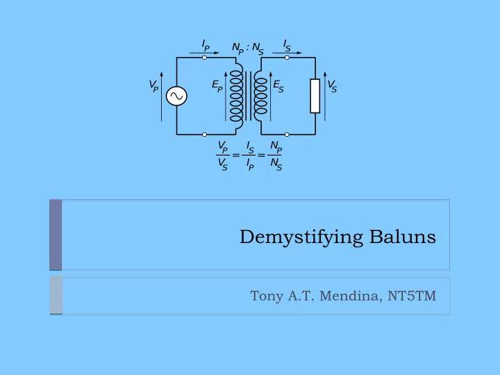
SLIDE 1 Demystifying Baluns
Tony A.T. Mendina, NT5TM
V
P
E
P
V
S
E
S
IP IS N
P
N
S
: V
P
V
S
IP IS N
P
N
S
= =
SLIDE 2 2
What’s all this, then?
A balun is “an electrical device that converts between a balanced signal and an unbalanced signal.” It might change the voltage and the current—the impedance—but it doesn’t have to. We’re often confused about whether we need a balun, and what kind we need if we do. Worse, some of us, myself included, have been confused about what is meant when we say “balanced” or “unbalanced.” We generally start our ham career by thinking that the difference is pretty simple.
https://en.wikipedia.org/wiki/Balun
SLIDE 3 3
Balanced vs. Unbalanced Transmission Lines
Obviously, these are balanced lines: And this unbalanced. Simple, right?
https://en.wikipedia.org/wiki/Coaxial_cable
SLIDE 4 4
Balanced vs. Unbalanced Transmission Lines
Is this line balanced? It uses twin lead! Right? So it must be…? Why isn’t it?
https://en.wikipedia.org/ https://columbiawire.ph/
SLIDE 5 5
Balanced vs. Unbalanced Transmission Lines
The reality is that you can’t actually tell if a line is balanced by its
- shape. It’s all about the ground (whether circuit common or actual
earth). A balanced transmission line has:
- Equal and opposite currents between its conductors
- Currents 180 degrees out of phase
- An equal impedance to ground (or the environment) from both of its
conductors at any point An unbalanced transmission line can still have:
- Equal and opposite currents between its conductors
- Currents 180 degrees out of phase
And still be unbalanced. In fact, inside of coax, you will always find equal and opposite currents that are 180 degrees out of phase.
SLIDE 6 6
Balanced vs. Unbalanced Transmission Lines
What makes most coaxial cable an unbalanced line is the same thing that makes your house wiring an unbalanced line— Part of it is connected to ground. That’s really it. If your coax did not have one side connected to ground, it could be
- balanced. It has nothing to do with the shape of the conductors.
SLIDE 7
7
Balanced vs. Unbalanced Antennas
Balance is also confusing because people speak about antennas as balanced. Sometimes, they just mean “symmetrical.” But other times, they mean the same thing as with a feedline. Equal and opposite currents, out of phase, with equal impedances to the environment in each corresponding part.
SLIDE 8 8
Balanced vs. Unbalanced Antennas
This symmetrical dipole is up in the clear, and is probably almost
- balanced. (Nothing’s perfect.)
SLIDE 9 9
Balanced vs. Unbalanced Antennas
Small loops are usually well-balanced, too.
https://en.wikipedia.org/wiki/Loop_antenna
SLIDE 10 10
Balanced vs. Unbalanced Antennas
The part of this antenna that’s near the hut will have a different impedance to ground than the other part. Whether coax or balanced line is used, there will be an “antenna current” in the feedline.
https://en.wikipedia.org/wiki/Steel_building
SLIDE 11
11
Balanced vs. Unbalanced Antennas
A ground-plane vertical is unbalanced. The radials will have a much lower impedance to ground than the vertical element does. You can feed it with coax or twin lead...there will still be “common mode.”
SLIDE 12 12
Balanced vs. Unbalanced Antennas
An unequal impedance to ground in any part of your antenna system, whether the feedline or the antenna, may cause “common mode” current. The part of current in your transmission line that isn’t equal and
- pposite in the pair of conductors is called “imbalance current,”
“antenna current,” or “common mode.” It can be caused by a received signal, or a transmitted one.
SLIDE 13 13
Balanced vs. Unbalanced Antennas
But why do we care? Is common mode current a problem? Is balance something we need? Does an antenna need balance to work well? Does a balanced feedline work better?
https://en.wikipedia.org/wiki/Arecibo_Observatory
SLIDE 14
14
Why a balun?
Assume a perfectly balanced dipole. What’s I3? Common-mode. Why?
SLIDE 15
15
Why a balun?
Because the coax is connected to the ground through its shield, the two arms of the dipole do not have an equal impedance to ground, and a common-mode current will flow on the outside of the cable.
SLIDE 16 16
Why a balun?
An antenna does not need to be balanced to work well! A balanced antenna does not make your coax balanced. Some antennas like the OCFD are deliberately not balanced, and are still fun. Balancing your feedline and eliminating common-mode might:
- Reduce RFI to appliances in your house
- Reduce received signal interference
- Eliminate “RF in the shack”
Eliminating common mode currents will:
- Make your VSWR more predictable
- Make your antenna pattern more predictable
A balanced feedline will not:
- Lower your cholesterol
- Make your antenna more efficient or your station more powerful
SLIDE 17 17
Why a balun?
I3 is a problem, if:
- You need a reliable antenna
pattern...that station in Shreveport always calls CQ on top of “the rare one”
changes when your feedline length changes
- You are picking up interference
from equipment near your feedline
- Your metal microphone or rig
gives you “bites”
- Your auto-tuner randomly re-
tunes when a bird lands on your coax
- Your transmissions trigger your
smoke alarms or turn off your A/C I3 is not a problem if:
- You don’t care about your
antenna pattern, or
- You want feedline radiation to
fill in the gaps
- You experience no problems
with RF in the shack
- You don’t receive interference
from your TV, computer, or
- ther appliances
- You don’t transmit
interference to appliances near your coax
- Your feedlines are electrically
short (1/8λ) at the frequencies where you use them
- Your antenna is used on one
frequency, and the feedline is an odd multiple of ¼λ
SLIDE 18 18
How a balun works
To get rid of that pesky I3, it would be great if we could just cut the coax shield But that would be really bad. So, we have to do something that interrupts the current on the outside of the coax. Why do we only care about the outside? Skin effect! A current that isn’t equal and
- pposite can only travel on the outside of our coax.
https://en.wikipedia.org/wiki/Skin_effect
SLIDE 19 19
How a balun works
We could interrupt the coax with a 1:1 transformer, but traditional transformers are not popular for amateur use. Their bandwidth is more limited and their losses are higher than if we just used transmission line to construct our balun. Coax works well from audio frequencies up through UHF; transformers can’t match that.
https://en.wikipedia.org/wiki/Balun
V
P
E
P
V
S
E
S
IP IS N
P
N
S
: V
P
V
S
IP IS N
P
N
S
= =
SLIDE 20 20
How a balun works
Because most rigs have an unbalanced output, and the inside and
- utside of the coax shield are separate wires at RF, we can balance
- ur transmission line and allow only the equal and opposite currents to
flow by impeding the current path on the outside of the coax. So the ground will no longer matter, and both the center conductor and the inside of the shield will have an equal impedance to ground—right through the output of our rig—just as we desire.
https://arrl.org/
SLIDE 21 21
How a balun works
By setting up an inductive coil, or adding ferrites to hugely increase the self-inductance of the coax shield, we increase the impedance of the outside of the coax. Common-mode currents don’t flow, or get turned into heat.
https://en.wikipedia.org/wiki/Balun https://www.qsl.net/ta1dx/amator/broadband_baluns.htm https://www.arrl.org/
SLIDE 22 22
Building and Using Baluns
Let’s talk about some practical ways to block common-mode current
- n your transmission lines.
Remember, we’re not concerned about any impedance transformation. We’re concerned first and foremost with “floating” our feedline above the ground.
SLIDE 23 23
Building and Using Baluns
There are really only two references you need.
- Jim Brown’s site: K9YC.COM
- http://k9yc.com/publish.htm
- http://k9yc.com/RFI-Ham.pdf
- http://k9yc.com/2018Cookbook.pdf
- The ARRL Antenna Book, 24th edition
- http://www.arrl.org/arrl-antenna-book
- Yes, you have to buy it
- Chapter 24 has all the latest balun information
It’s important to check a reference work describing the balun you plan to build, because it’s easy to accidentally build something other than what you intended. There’s lots of great balun testing information on-line! Older versions of the “RFI-HAM.pdf” have many 1:1 balun designs.
SLIDE 24 24
Building and Using Baluns
Surely, he’ll talk about current vs. voltage baluns, right?
- My name’s not Shirley, and that’s the big building where all the
doctors are.
- Any impedance transformer will have to change both the current and
the voltage!
- The only real “current” baluns are those that choke off the common
mode/imbalance/antenna current.
- I’ll talk more about this at a DARC Lecture and Lab, but if you want
to transform impedance, use an impedance transformer.
- If you want to produce balanced currents, use a 1:1 current balun.
- It’s OK to combine both a 1:1 current balun and an impedance
transformer in series.
- Beware! Impedance transformers do not perform predictably with
reactive loads. You might think that 400x + 40j becomes 100x + 10j, and be surprised by a load of 13x – 322j.
- My advice: unless you’re working into a predictable load, like a
single-band folded dipole, just focus on blocking the common-mode current and let your antenna matching unit deal with the impedance transformation.
SLIDE 25 25
Common Balun Types
The sleeve balun is famous among radio amateurs; most of us have folded the braid back on our coax, right? But it turns out...that doesn’t
- work. Construction tip: Don’t build one.
SLIDE 26
26
Common Balun Types
The coax loop is unique, in that it provides a balanced antenna connection, a 4:1 impedance transformation, and lots of common mode current, thus balancing your antenna connection and not your feed line. Notice how the grounded shield never touches the antenna? Construction tip: Be careful of the velocity factor! It only applies to the part of the ½-wave loop that has foam and shielding. Bandwidth is 1%. The coax center conductor may snap if it’s solid wire.
SLIDE 27
27
Common Balun Types
Don’t want to transform the impedance? Use a ¼-¾ coax balun. Again, the velocity factor is important, but the bandwidth is reported to be larger, up to 10%. This is a balun, because the antenna feed point is now isolated from the ground. I have never built this type, but it’s popular for single-band beams.
SLIDE 28
28
Common Balun Types
The bifilar choke causes an impedance “bump,” but is useful with both coax and twin lead. It’s less favored now than just winding coax around ferrite. Trivia: lots of common wires, separated by their own insulation thickness, form a 100-ohm transmission line. Check on-line references for the number of turns. Use mix 31 ferrite.
SLIDE 29
29
Common Balun Types
Walt Maxwell, W2DU, made this choke famous. Use plenty of beads! Type 31 works well; this particular example used type 43 ferrite, because that’s what came in the kit. Construction tip: in general, these “bead sleeve” baluns are 10-12 inches long. If you need more length to get the impedance you want, it’s probably best to select a different type.
SLIDE 30
30
Common Balun Types
Mix 31 ferrite is also available from on-line sellers the form of a “big clamp on.” This is a great tool...practically a nuclear weapon...for stamping out common-mode current in all sorts of things, like the cord from your generator, or the feedline to a “strange antenna challenge” fireplace used as a 20-meter vertical.
SLIDE 31
31
Common Balun Types
UPDATE: A reliable source has told me that these clamp-ons have a poor reputation for performance if the mating surfaces are even slightly dirty...but mine still work well enough for power cord use, especially if I use two of them.
SLIDE 32 32
Common Balun Types
This is the preferred form of modern 1:1 current balun. A section of coax is coiled around a choke, preserving constant impedance. See the Antenna Book, or K9YC.COM, for simple instructions. Use mix 31
- ferrite. It’s hard to get these wrong. Construction tip: RG 400 is a type
- f tough, high-end RG 58, and lets you fit in more turns.
SLIDE 33
33
Common Balun Types
The ugly balun is free! Beware, though. Because its coils have both capacitance and inductance, it resembles a trap, like you’d use in a dipole...with high impedance only on one frequency. Check the Antenna Book or web for number of turns. The ugly balun also adds coax loss, if that matters in your situation. Consistency is also an issue with this type.
SLIDE 34
34
A Technical Note
I like baluns, but they are not magical. If the I3 on your coax was facing a reactance of j-200, and your balun adds j+200, the balun will actually increase common-mode current. There’s a helpful web page on this at http://www.karinya.net/g3txq/chokes/
SLIDE 35
35
What do you think?
What balun myths have YOU had to un-learn during your career? What worked for you? Did your coax melt? Mine rusted...
SLIDE 36
36
Thank you for your participation! We’ll talk more about baluns, un-uns, and impedance transformers at a future DARC Lecture and Lab