Data Hazards Timing error or race between dependent instructions - - PowerPoint PPT Presentation

data hazards
SMART_READER_LITE
LIVE PREVIEW

Data Hazards Timing error or race between dependent instructions - - PowerPoint PPT Presentation

Data Hazards Timing error or race between dependent instructions WAW Dependency/Hazard: Between instructions that write to the same register (or memory location) ADD R1 , R2, R3 LD R1 , 100(R5) WAR Dependency/Hazard


slide-1
SLIDE 1

Data Hazards

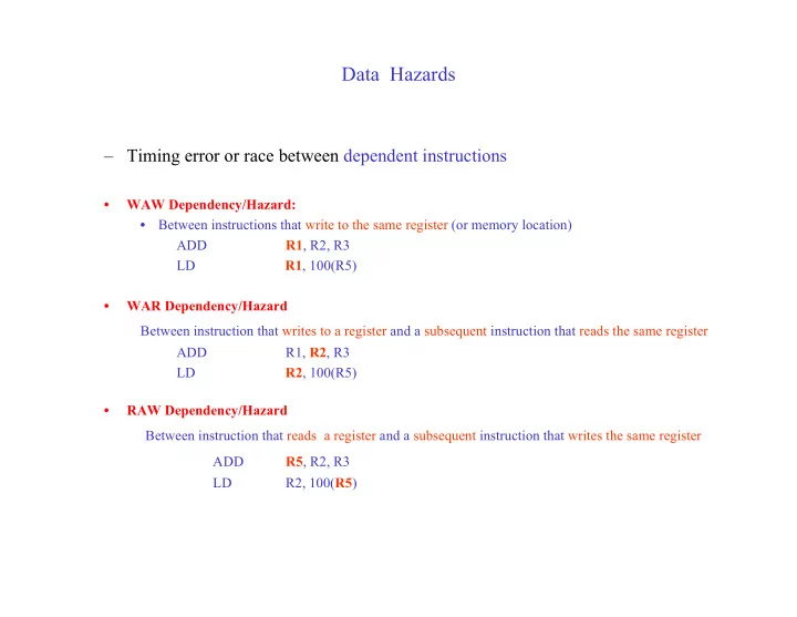
– Timing error or race between dependent instructions

  • WAW Dependency/Hazard:
  • Between instructions that write to the same register (or memory location)

ADD R1, R2, R3 LD R1, 100(R5)

  • WAR Dependency/Hazard

Between instruction that writes to a register and a subsequent instruction that reads the same register ADD R1, R2, R3 LD R2, 100(R5)

  • RAW Dependency/Hazard

Between instruction that reads a register and a subsequent instruction that writes the same register

ADD R5, R2, R3 LD R2, 100(R5)

slide-2
SLIDE 2

RAW Hazards

  • 5-stage pipeline has no WAR and WAW Hazards
  • RAW Hazards
  • Simple solutions based on Stall
  • Software Solution
  • Hardware Solution
  • Reducing Performance Penalty
  • Software
  • Hardware
slide-3
SLIDE 3

RAW Hazard

A : ADD R1, R2, R3 B : ADD R4, R1, R5 Hazard possible since register reads occur earlier stage than writes

  • A writes R1 at cycle 5
  • B may read R1 at cycle 3, 4 or 5
  • If B reads R1 at cycle 3 or 4: RAW Hazard
  • If B reads R1 at cycle 5 or later; No Hazard
  • Example: A and B consecutive instructions

1 2 3 4 5 6 IF ID EX MEM WB IF ID EX MEM WB A B Instruction B reads stale value in R1, before its update by A

slide-4
SLIDE 4

Solutions for RAW Hazards

  • Correctness:

a) Introduce stall cycles (delays) to avoid hazard

  • Delay second instruction till write is complete
  • Software
  • Insert NOPs into delay slots between the instructions
  • At least 2 independent instructions
  • Hardware
  • Hazard Detection Unit detects the hazard and stalls the pipeline
slide-5
SLIDE 5

Compiler Inserted NOPs

Consecutive instructions A, B forced apart by 2 NOPs to avoid RAW hazard

MEM 2 3 4 5 6 ID EX WB 7 1 IF IF ID EX MEM 8 WB A NOP NOP B

  • NOPS add 2 cycles to the execution time
  • Suppose 40% of ALU instructions are followed by a dependent ALU instruction with

separation 1 or 2. 90% of instructions are ALU instructions Worst-case CPI = 1.0 + 90% x 40% x 2 = 1.72

A : ADD R1, R2, R3 B : ADD R4, R1, R5

slide-6
SLIDE 6

Compiler Inserted NOPS

IF EX ID MEM WB A IF EX ID MEM WB A IF EX ID MEM WB A IF EX ID MEM WB C A IF EX ID MEM WB D B A EX ID MEM WB B T=1 T=2 T=3 T=4 T=5 T=6 C B IF

slide-7
SLIDE 7

Hardware-Controlled Pipeline Stall

A : ADD R1, R2, R3 B : ADD R4, R1, R2

  • Hazard Detection unit detects hazardous RAW dependency
  • Stalls the pipeline till hazard is avoided
  • Delays B by 2 cycles

MEM 2 3 4 5 6 ID EX WB IF ID ID ID EX 7 MEM 1 IF IF IF IF ID EX 8 WB MEM A B C 9 WB IF ID EX MEM C C D

slide-8
SLIDE 8

Hardware Controlled Pipeline Stall

IF EX ID MEM WB P C

A : ADD R1, R2, R3 B : ADD R4, R1, R2 C:

IF EX ID MEM WB P C T = 2 T = 3 IF EX ID MEM WB P C T = 4

A A A B B

Stall Cycle!!

FREEZE NOP NORMAL

slide-9
SLIDE 9

Hardware Controlled Pipeline Stall

IF EX ID MEM WB P C IF EX ID MEM WB P C IF EX ID MEM WB P C T = 4 T = 5 T = 6

  • Instruction B held in IF/ID register until A reaches WB stage
  • Internally generated NOPs propagated forward while B is stalled

B B B A A

Stall again!

slide-10
SLIDE 10

Hazard Detection Unit

IF EX ID MEM WB P C

HDU

Freeze register: do not update Insert NOP

Stall Pipeline if instruction in IF/ID register reads register W and the instruction in either the ID/EX register or the EX/MEM register will write register W W is in either the rt (RI) or rd (RR) field of the writing instruction and the rs or rt field of the reading instruction

B

slide-11
SLIDE 11

Operation of Hazard Detection Unit

Compare Register numbers of the READ REGISTER of instruction in IF/ID Pipeline Register with the WRITE REGISTER of the instruction in the ID/EX Pipeline Register and WRITE REGISTER of the the instruction in the EX/MEM Pipeline Register If any of the comparisons succeed: Insert Stall Cycle FREEZE PC and IF/ID Pipeline Register Insert NOP into ID/EX Pipeline Register Write Register Read Register R-R rd rs, rt R-I rt rs LD rt rs SD

  • rs, rt

Bcc

  • rs

Bcc

  • rs, rt

12

slide-12
SLIDE 12

Solutions for RAW Hazards

  • Correctness:
  • Introduce stall cycles (delays) to avoid hazard manifestation
  • compiler
  • hardware
  • Correctness + Performance:
  • Reduce or eliminate stall cycles
  • program optimization
  • additional hardware
  • Combination
  • Mask delay
  • overlap stall cycles with other useful operations

13

slide-13
SLIDE 13

Solutions for RAW Hazards

  • Correctness + Performance

a) Reduce or eliminate stall cycles

  • Software
  • Restructure code to fill delay slots with independent instructions
  • (Compiler Optimizations)
  • Hardware
  • Forwarding (Register bypass)
  • Provide alternate datapaths within the pipeline to communicate values
  • Instruction gets value directly from source instruction bypassing the register
  • Combination
  • Load Delay Slot
  • Mask delay

b) Overlap stall cycles with other useful operations

14

slide-14
SLIDE 14

Performance Issues

NOPS and stalls consume cycles and reduce throughput

  • Software

Reorganize assembly code

Move an independent instruction in the delay slot (where the NOP was inserted) ADD R1, R2, R3 ADD R1, R2, R3 SUB R4, R1, R5 XOR R3, R2, R7 XOR R3, R2, R7 AND R8, R7, R7 AND R8, R7, R7 SUB R4, R1, R5

Original Code Optimized Code

  • Hardware:

Forwarding and Bypass hardware Compiler Optimization

15

slide-15
SLIDE 15

Forwarding

Example: Two R-R Type instructions with RAW dependencies A : ADD R1, R2, R3 B : ADD R4, R1, R2

What is the effect of these two instructions?

  • Value to be written into R1 by A computed in EX stage (cycle 3)
  • Value used by B in EX stage (cycle 4)

1 2 3 4 5 6 IF ID EX MEM WB IF ID EX MEM WB A B

16

slide-16
SLIDE 16

Forwarding

Example: Two R-R Type instructions with RAW dependencies A : ADD R1, R2, R3 B : ADD R4, R1, R2

  • Why wait till value written into register R1?
  • Why use R1 to communicate the result of A to B ?
  • Directly forward result of A to B
  • Provide alternate datapaths from ALU output back to its input

1 2 3 4 5 6 IF ID EX MEM WB IF ID EX MEM WB A B

17

slide-17
SLIDE 17

Forwarding R-R Type Instructions

A : ADD R1, R2, R3 B : ADD R4, R1, R5 Result of A in EX/MEM register at end of cycle 3 Stale R1 value read by B in ID/EX register at end of cycle 3 B uses value forwarded from EX/MEM register in EX stage (cycle 4)

IF EX ID MEM WB

M U X M U X

P C

(R5) (R1)

B A

18

slide-18
SLIDE 18

Forwarding

Example: Two R-R Type instructions with RAW dependencies A : ADD R1, R2, R3 X: ADD R6, R7, R8 B : ADD R4, R1, R2 WB MEM EX ID IF B WB MEM EX ID IF X WB MEM EX ID IF A 7 6 5 4 3 2 1

21

slide-19
SLIDE 19

Forwarding R-R Type Instruction

A : ADD R1, R2, R3 X: ADD R6, R7, R8 B : ADD R4, R1, R5

  • Result of A in MEM/WB register at end of cycle 4
  • Stale R1 value read by B in ID/EX register at end of cycle 4

B uses value forwarded from MEM/WB register in EX stage (cycle 5)

P C IF EX ID MEM WB

M U X M U X

(R5)

B A X

(R1)

19

slide-20
SLIDE 20

Forwarding R-R Type Instruction

A : ADD R1, R2, R3 B: ADD R1, R6, R7 C : ADD R4, R1, R5

  • Result of A in MEM/WB register at end of cycle 4
  • Result of B in EX/MEM register at end of cycle 4
  • Stale R1 value read by C in ID/EX register at end of cycle 4
  • C uses value forwarded from EX/MEM register in EX stage (cycle 5)

P C IF EX ID MEM WB

M U X M U X

(R5) C B A (R1)

20

slide-21
SLIDE 21

Forwarding for Load Instructions

Example:

A: LD

R1, 0(R2) B: ADD R3, R1, R4 Forwarding is insufficient to resolve RAW data hazard A obtains value from memory at end of cycle 4 B computes with R1 during cycle 4

1 2 3 4 5 6 IF ID EX MEM WB IF ID EX MEM WB A B

22

slide-22
SLIDE 22

Load Hazard

  • Requires Delay even with Forwarding hardware
  • In DLX the delay is done by software:
  • Instruction following LD executes in the Load Delay slot
  • Load Delay slot exposed to the programmer
  • Software must ensure that the instruction following a LD must not have

RAW dependence with the LD

  • Explicitly insert NOP (or independent instruction) after load instruction

23

slide-23
SLIDE 23

Load Hazard

1. Need to delay B for 1 cycle (a) Software: Add NOP (or independent instruction) between A and B OR (b) Hardware: Stall B for 1 cycle in ID stage using HDU 2. Forward data read from memory (in MEM/WB register) to EX stage

1 2 3 4 5 6 IF ID EX MEM WB IF ID ID EX MEM A B 7 WB IF ID EX MEM WB 7 1 2 3 4 5 6 IF ID EX MEM WB A NOP B

24

slide-24
SLIDE 24

LD with Stall and Forwarding

IF EX ID MEM WB

M U X M U X

P C IF EX ID MEM WB

M U X M U X

  • LD in ID/EX
  • Dependent ALU op in ID/EX
  • Hazard Detection unit delays dependent

instruction for 1 cycle

  • Freeze PC and IF/ID registers
  • Insert NOP into ID/EX

Stall Step: Insert NOP P C

LD LD

NOP

B B

NOP

25

slide-25
SLIDE 25

LD with Stalls and Forwarding

Forwarding Step: Forward data from MEM/WB to ALU Input

IF EX ID MEM WB

M U X M U X

  • LD in MEM/WB
  • Dependent ALU instruction in ID/EX
  • Forward output from MEM/WB to ALU input

P C

B LD NOP

What if dependent instruction was 2 cycles behind the LD? LD and SD combinations? Other instruction combinations?

NOP

26