DAMAGE RESISTANCE OF GRAPHITE/EPOXY LAMINATES WITH A FASTENER - - PDF document

damage resistance of graphite epoxy laminates with a
SMART_READER_LITE
LIVE PREVIEW

DAMAGE RESISTANCE OF GRAPHITE/EPOXY LAMINATES WITH A FASTENER - - PDF document

18 TH INTERNATIONAL CONFERENCE ON COMPOSITE MATERIALS DAMAGE RESISTANCE OF GRAPHITE/EPOXY LAMINATES WITH A FASTENER SUBJECTED TO ARTIFICIAL LIGHTNING Y. Hirano 1 *, C. Reurings 2 , Y. Iwahori 1 1 Japan Aerospace Exploration Agency (JAXA), Advanced


slide-1
SLIDE 1

18TH INTERNATIONAL CONFERENCE ON COMPOSITE MATERIALS

1 Introduction The excellent specific properties of carbon fiber reinforced plastics (CFRP) drive the large-scale application in weight critical structures, such as automotive and aerospace structures. The Airbus A350 XWB, scheduled for 2014, is claimed to be made of composites for 53% [1]. Unlike the often replaced aluminum, carbon fiber laminate skins require special attention in design regarding internal

  • damage. Both mechanical impact and lightning

strike are known to cause internal damage, which greatly reduces the residual strength [2,3]. Results have shown that the presence of a fastener increases both the damage and the reduction in residual compressive stress due to a lightning test [4]. Since fasteners are often present in the outer skin of aircraft and they are therefore likely to be struck by lightning, it is essential to understand the resulting

  • damage. The investigation presented here focuses on

understanding the effect of the fit of the fastener on the damage caused by an artificial lightning strike. The lightning struck specimens have been examined by visual, non-destructive and micrographic inspection. 2 Experimental procedure 2.1 Specimens The laminates are made of prepregs consisting of IM600 graphite fiber and #133 epoxy produced by Toho Tenax. Prepreg molding in an autoclave was followed by a recommended cure cycle. The layup

  • f the laminates is [45/0/-45/90]4s and the applied

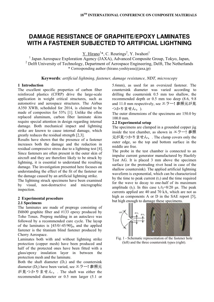
fastener is the titanium blind fastener produced by Cherry Aerospace. Laminates both with and without lightning strike protection (copper mesh) have been produced and half of the protected ones have been fitted with a glass/epoxy insulation layer in between the protection mesh and the laminate. Both the shaft diameter (D1) and the countersink diameter (D2) have been varied, see エラー! 参照元 が見つかりません。. The shaft was either the recommended diameter or 0.5 mm larger (5.1 or 5.6mm), as used for an oversized fastener. The countersink diameter was varied according to drilling the countersink 0.5 mm too shallow, the recommended depth or 0.5 mm too deep (8.6, 9.8 and 11.0 mm respectively, see エラー! 参照元が見 つかりません。). The outer dimensions of the specimens are 150.0 by 100.0 mm. 2.2 Experimental setup The specimens are clamped in a grounded copper jig inside the test chamber, as shown in エラー! 参照 元が見つかりません。. The clamp covers only the

  • uter edge, so the top and bottom surface in the

middle are free. The probe in the test chamber is connected to an impulse current generator manufactured by Haefely Test AG. It is placed 3 mm above the specimen surface (or the protruding rivet head in case of the shallow countersink). The applied artificial lightning waveform is exponential, which can be characterized by the time to peak current (t1) and the time required for the wave to decay to one-half of its maximum amplitude (t2). In this case t1/t2=8/20 μs. The peak currents applied are 40 and 70 kA, which are not as high as components A or D in the SAE report [5], but high enough to damage these specimens.

  • Fig. 1 - Schematic representation of the fastener hole

(left) and the three countersink types (right).

DAMAGE RESISTANCE OF GRAPHITE/EPOXY LAMINATES WITH A FASTENER SUBJECTED TO ARTIFICIAL LIGHTNING

  • Y. Hirano1*, C. Reurings2, Y. Iwahori1

1 Japan Aerospace Exploration Agency (JAXA), Advanced Composite Group, Tokyo, Japan, 2 Delft University of Technology, Department of Aerospace Engineering, Delft, The Netherlands

* Corresponding author (hirano.yoshiyasu@jaxa.jp)

Keywords: artificial lightning, fastener, damage resistance, NDT, microscopy

slide-2
SLIDE 2
  • Fig. 2 - The grounded copper jig with a clamped

specimen and the lightning probe above it.

3 Results and discussion To analyze internal damage a 400 kHz air-coupled through-transmission ultrasonic scanner is used. Through-transmission ultrasonic scanning gives the projected damage area. Using visual observation and these c-scan images, some preliminary observations can be made. Only the unprotected specimens at 40 kA are discussed. Visual inspection shows that the initially protruding fastener head for the smallest countersink is forced

  • inward. Similar for the initially perfect countersink

with large shaft diameter; the fastener head is below the laminate surface after the strike. The most likely cause is the acoustic shock and the accompanying high pressure [6]. Also observed among the smallest countersink specimens is outer ply separation; strips

  • f the outer +45° layer have separated, starting at the

fastener hole, some of which completely up to the clamped edge. The width of the separated region is not much wider than the hole, see Fig. 3. In some cases strips of the 0° layer underneath have separated as well. All specimens show cracks in the fiber direction of the outer layer at the bottom surface, surrounding the fastener stem (see Fig. 3). This confirms what has been observed in previous studies [2,4]; the presence of a fastener causes the damage to be through the full thickness of the laminate. The c-scan images for these specimens show internal damage fanning outward from the hole, mainly in the two other ply directions (-45° and 90°); the separation seems to have consumed most of the energy in the first two layers. As an example, a comparison of obtained c-scan result is shown in Fig.

  • 4. Looking at the projected damage area as a

function of the countersink depth (Fig. 5), shows that the recommended countersink depth is not the best from a damage area point of view; the deepest countersink has the smallest projected area for both normal and large shaft diameter. In this examination, only one specimen of each configuration was tested at a given intensity. Therefore extra tests under the identical condition for each configuration are required to discuss the scatter and general trends.

  • Fig. 3 Magnified view of the front and back (shallow

countersink, large shaft diameter). a) shallow b) recommended c) deep

  • Fig. 4 C-scan images of normal shaft diameter.
  • Fig. 5 - Projected damage area vs. countersink depth.

4 Conclusions A too small countersink depth leads to increased surface damage, including separation of the outer

  • plies. In some cases the fastener is forced inward

due to the high pressure, which will most likely affect the joint strength. The largest countersink depth shows the smallest projected internal damage area for both shaft diameters. No clear trend has been observed so far concerning the effect of shaft diameter increase. So far only the specimens without lightning protection and at the lowest peak current intensity have been discussed. The full paper will include more types of analysis, on all the specimens and at all intensities. References

[1] G. Marsch. “Airbus A350 XWB update”. Reinforced plastics, Vol. 45, No. 6, pp 20-24, 2010. [2] P. Feraboli, H. Kawakami. “Damage of carbon/epoxy composite plates subjected to mechanical impact and simulated lightning”. Journal of Aircraft, Vol. 47, No. 3, pp 999-1012, 2010. [3] Y. Hirano, S. Katsumata, Y. Iwahori, A. Todoroki. “Artificial lightning testing on graphite/epoxy 0º 0º

slide-3
SLIDE 3

3 PAPER TITLE composite laminate”. Composites: Part A, Vol. 41,

  • No. 10, pp 1461-1470, 2010.

[4] P. Feraboli, M. Miller. “Damage resistance and tolerance of carbon/epoxy composite coupons subjected to simulated lightning strike”. Composites: Part A, Vol. 40, No. 6-7, pp 954-967, 2009. [5] SAE. “Aircraft lightning environment and related test waveforms standard”. Committee report, AE4L-97-4; 1997. [6] E. Rupke. “Lightning direct effects handbook”. AGATE-WP3.1-031027-043-Design Guideline, 2002.