
SLIDE 1
2/18/2010 1
Buckling Resistance of Frames Buckling Resistance of Frames and and Requirements for elastic and Requirements for elastic and Buckling Resistance of Frames Buckling Resistance of Frames and and Requirements for elastic and Requirements for elastic and advanced structural analysis advanced structural analysis advanced structural analysis advanced structural analysis
Prof Dr Prof Dr Shahrin Shahrin Mohammad Mohammad Assoc Prof Dr Ahmad Assoc Prof Dr Ahmad Baharudin Baharudin Abdul Abdul Rahman Rahman 24 24th
th Feb 2010
Feb 2010
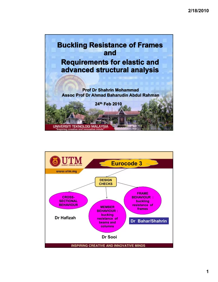
Eurocode 3
DESIGN CHECKS MEMBER BEHAVIOUR : bucking CHECKS CROSS- SECTIONAL BEHAVIOUR FRAME BEHAVIOUR : buckling resistance of frames bucking resistance of beams and columns
Dr Hafizah Dr Sooi Dr Bahar/Shahrin