
SLIDE 1
DA-conversion, usually PWM
William Sandqvist william@kth.se
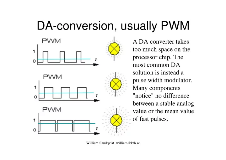
A DA converter takes too much space on the processor chip. The most common DA solution is instead a pulse width modulator. Many components "notice" no difference between a stable analog value or the mean value
- f fast pulses.