
SLIDE 1
1
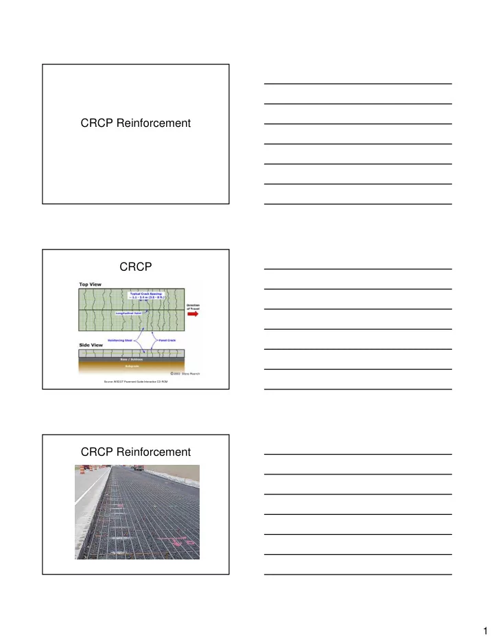
CRCP Reinforcement CRCP
Source: WSDOT Pavement Guide Interactive CD-ROM
CRCP Reinforcement CRCP Source: WSDOT Pavement Guide Interactive - - PDF document
CRCP Reinforcement CRCP Source: WSDOT Pavement Guide Interactive CD-ROM CRCP Reinforcement 1 Design Variables Slab thickness, D (in) Slab width, W s (in) Modulus of subgrade reaction, k eff (psi/in) Design temperature drop,
Source: WSDOT Pavement Guide Interactive CD-ROM
0.0002 700 or more 0.0003 600 0.00045 500 0.0006 400 0.0008 300 or less (in/in) (psi) Coefficient Tensile Strength Shrinkage Indirect
60,000 67,000 67,000 800 or more 59,000 65,000 67,000 700 58,000 63,000 67,000 600 56,000 61,000 67,000 500 55,000 60,000 67,000 400 54,000 57,000 65,000 300 or less
Indirect Tensile Strength (psi) Reinforcing Bar Size
Minimize potential for punchouts
Minimize potential for spalling
Minimize water infiltration and potential for spalling
Prevent failure of reinforcing steel
1.15 6.70 2.19 t s c 5.20 4.60 1.79 w
0.25 1.457 0.476 t s c max 1.13 0.217 0.389 w
0.25 1.457 0.476 t s c 1 min 1.13 0.217 0.389 w
6.53 2.20 t 4.91 4.55 w
1.435 0.484 t 2 min 1.079 0.220 w
4.09 0.425 t d s 3.14 2.74 0.494 w
1.493 0.155 t d 3 min 1.146 0.365 0.180 w s c
1 2 3 min min min min
min s min 2
max s max 2
+ + + = − = + +
1.457 0.25 0.476 max 1.13 0.217 0.389
3.5 f 1.062 1 0.6 1 0.66 1 0.75 P 1 0.70% 1 0.23 1 0.3 t
0.25 1.457 0.476 t s b c max 1.13 0.217 0.389 w c
+ + + = − = + +
1.457 0.25 0.476 1 min 1.13 0.217 0.389
8.0 1.062 1 0.6 1 0.66 1 0.75 P 1 0.42% 1 0.23 f 0.3 t 1
0.25 1.457 0.476 t s b c 1 min 1.13 0.217 0.389 w c
1.435 0.484 t b 2 min 1.079 0.220 w
1.435 0.484 2 min 1.079 0.220
0.358 1 0.6 1 0.75 P 1 0.50% 1 0.2 0.04 in 3 + + = − = +
1.493 0.155 t d 3 min 1.146 0.365 0.180 w s c
1.493 0.155 3 min 1.146 0.365 0.180
50.834 1 0.6 1 0.6 P 1 0.52% 1 0.2 58,0 3 00 3 1 0. + + = − = + +
min
min s min 2 2 b
max s max 2 2 b
2 2 b s
1.15 6.70 2.19 t s b c 5.20 4.60 1.79 w c
6.70 1.15 2.19 5.20 4.60 1.79
6.53 2.20 t b 4.91 4.55 w
6.53 2.20 4.91 4.55
4.09 0.425 t d s 3.14 2.74 0.494 w c
4.09 0.425 s 3.14 2.74 0.494