COOLING TOWER PUNJAB STATE POWER CORPORATION LIMITED Introduction - - PowerPoint PPT Presentation

cooling tower
SMART_READER_LITE
LIVE PREVIEW

COOLING TOWER PUNJAB STATE POWER CORPORATION LIMITED Introduction - - PowerPoint PPT Presentation

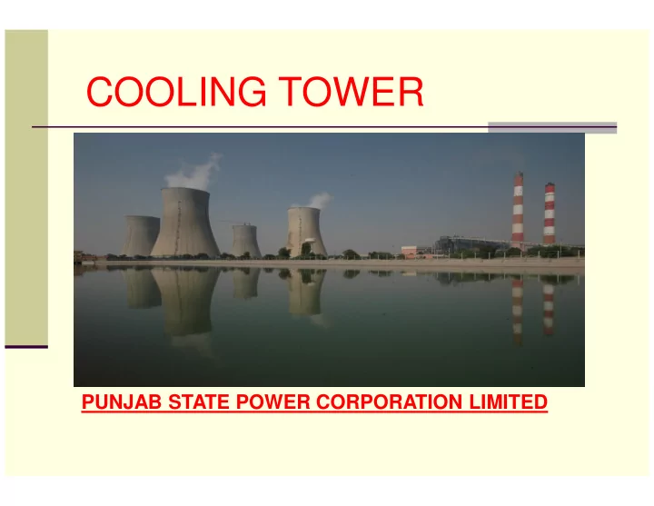
COOLING TOWER PUNJAB STATE POWER CORPORATION LIMITED Introduction Cooling towers are commonly used to remove excess heat that is generated & represent a relatively inexpensive and dependable means of removing low-grade heat from cooling


slide-1
SLIDE 1

PUNJAB STATE POWER CORPORATION LIMITED

COOLING TOWER

slide-2
SLIDE 2

Introduction

 Cooling towers are commonly used to remove

excess heat that is generated & represent a relatively inexpensive and dependable means of removing low-grade heat from cooling water.

 Cooling towers make use of evaporation whereby

some of the water is evaporated into a moving air stream and subsequently discharged into the atmosphere in the form of vapours.

slide-3
SLIDE 3

Classification of Cooling water

 Classification by build  Classification based on heat transfer method  Classification based on Air draft  Classification based on Air flow pattern

but I will limit my talk to a Air draft (Natural Draft) Cooling Tower

slide-4
SLIDE 4

Factors governing operation of Cooling water

 The dry-bulb and wet-bulb temperatures of the air  The temperature of warm water  The area of contact between air and hot water  The contact time between the air and the water  The air pressure drop  The desired temperature of the cooled water

slide-5
SLIDE 5

Natural Draft Tower

The natural draft or hyperbolic cooling tower makes use of the difference in temperature between the ambient air and the hotter air inside the tower. As hot air moves upwards through the tower (because hot air rises), fresh cool air is driven into the tower through an air inlet provided at the bottom.

slide-6
SLIDE 6

Components of Cooling Tower

 Structural Components

1. Cold water basin 2. Tower Framework 3. Water distribution System 4. Fill 5. Drift Eliminator 6. Casing / Shell Structure 7. Louvers

slide-7
SLIDE 7

Materials of Components of Cooling Tower

 Tower Material

1. Frame & Casing – Concrete & Steel 2. Fill - PVC/Polyproplene 3. Nozzles

  • PVC/Polyproplene
slide-8
SLIDE 8

Tower Problems

 Scale deposit  Fouling due to presence of silt ,dirt ,sand etc.  Microbiological growth due to presence of

microoganisms , Algae, fungi

 Corrosion of steel parts

slide-9
SLIDE 9

Operation Considerations

 Water make-up

To compensate the water loss due to :

  • 1. Evaporation ,
  • 2. Drift (water entrained in discharge vapor),

estimated to be About 0.2% of water supply

  • 3. Blow down (water released to discard solids).
slide-10
SLIDE 10

Cooling Tower parameters

Sr. No. Design Parameter CT- Stage I CT – Stage II 1. Total design capacity 33000cum / Hr. 36500 m3/hr 2. Height of top of tower above sill 120 m 104.625 m 3.

  • do- at throat

36.93 m 49.856 4.

  • do- at top

42.67 m 51.856 5 Dry Bulb Temp. 35.1 35.05 6 Design wet bulb Temp 28.5 28.25 7 Cold Water outlet Temp 32.5 33 8 Hot water Inlet Temp 42.5 41.1

9

PVC Fill

Size 1600x600x300 in two layers; munters type C-10-19 double folded edge on one side and with black UV Stabilization , 0.25 mm thick and having a flute size of 19mm

1220x1830 of varying depths of 915mm,1120mm &1525 mm of Paharpur M67 make

10

Basin Depth

2.8 m

2.0-2.30 m

slide-11
SLIDE 11

Cooling Water Analysis

Sr. No. Design Parameter Design Actual 1 Ph 7.5-8.00 8.4 2 Turbidity & Suspended solids

  • 100 ppm

6 – 7 50-60 ppm 3 Total dissolved solids 200-500 ppm 350-500 ppm 4 Ca-hardness as CaCo3 140 ppm 150-200 ppm 5 M -alkanity as CaCo3 140 ppm 104-120 ppm 6 Chlorides as Cl 40 ppm 40-70 ppm 7 Sulphates as SO4 140 ppm 125 – 180 ppm 8 Silica as Sio2 4 ppm 3.3 – 7.0 ppm

slide-12
SLIDE 12

Improving Energy Efficiency of Cooling Towers

1. Clearances around cooling towers needs to be adequate to ensure uninterrupted air intake or exhaust.

  • 2. Use right type of nozzles that do not clog & spray in a

more uniform water pattern. Square spray nozzles are clog free as compared to spray type nozzles.

  • 3. Increase contact surface and contact time between air

and water may be with the use of PVC Film Type fills by replacing splash bars.

  • 4. Clean distribution nozzles regularly.
  • 5. Optimize the blow down flow rate, taking into account

the cycles of concentration (COC)limit.

slide-13
SLIDE 13

Improving Energy Efficiency of Cooling Towers

  • 6. Keep the cooling water temperature to a minimum level by

(a) segregating high heat loads like furnaces, air compressors, DG sets and (b) isolating cooling towers from sensitive applications like A/C plants, condensers of captive power plant etc. 7. Monitor approach, effectiveness and cooling capacity to continuously optimize the cooling tower performance Seasonal variations be taken into consideration.

  • 8. Monitor liquid to gas ratio and cooling water flow rates and

amend these depending on the design values and seasonal

  • variations. For example: increase water loads during summer

and times when approach is high and increase air flow during monsoon times and when approach is low.

slide-14
SLIDE 14

Improving Energy Efficiency of Cooling Towers

  • 9. Increase COC improvement for water savings. The use
  • f water treatment chemicals, pretreatment such as

softening & pH adjustment , and other techniques can affect the acceptable range of cycles of concentration.

  • 10. Check cooling water pumps regularly to maximize

their efficiency.

slide-15
SLIDE 15

Some Problems & its remedy for Cooling Towers

Drift/carry-over of water outside the unit

  • 1. Uneven operation of spray nozzles

2 Blockage of the fills 3 Defective or displaced droplet eliminators 4 Excessive circulating water flow may be due to too high pumping head) 1 Adjust & clean the nozzle 2 Eliminate any dirt on the top of the fill or with suitable chemical pretreatment 3 Replace or realign the eliminators 4 Adjust the water flow-rate by means of the regulating valves. Check damage to the fill Lack of cooling and hence increase in temperatures owing to increased temperature range 1 Water flow below the design value 2 Irregular airflow or lack of air 3 Recycling of humid discharge air 4 Intake of hot air from other sources 5 Blocked spray nozzles (or even blocked water pipes) 6 Scaling of joints 7 Scaling of the fill pack 1 Regulated the flow by means of the valves 2 Ensure adequate clearance around cooling towers 3 Check the air descent velocity 4 Install deflectors 5 Clean the nozzles and/or the Tubes 6 Wash or replace the item 7 Clean or replace the material (washing with inhibited aqueous sulphuric acid is possible but long, complex and expensive)

slide-16
SLIDE 16

Problems Encountered at GHTP

Concrete Shell

Patches of dampness on external surface of RCC shell.

Minor cracks on staircase beams & columns.

Holes & Patches in the inside of shell Water distribution Pipes

Silt Deposit in the distribution pipes

Exposure of Concrete surface of Supports

Deposit of Scale / Corrosion of MS pipe surface PVC Fills

Green algae found on fills

Fills are almost choked with scale deposit mainly consisting of CaCo3 & sio2 & other organic matter.

water at operating COC is scaling in nature.

Pre chemical treatment / dozing be adopted to prevent organic growth. PVC Nozzles

Chocking of nozzles due to the presence of silt, clay, sand & scale deposits.

Nozzles are cleaned as a matter of routine in every shut down

Presence of algae, fungi & bacteria are causing biological fouling in Nozzles

Strainers & chemical treatment can be used to prevent biological fouling.

slide-17
SLIDE 17