Controlling DESIGN PRINCIPLE: To achieve a highly precise and - - PowerPoint PPT Presentation

controlling
SMART_READER_LITE
LIVE PREVIEW

Controlling DESIGN PRINCIPLE: To achieve a highly precise and - - PowerPoint PPT Presentation

Controlling Degrees of Freedom From a kinematic viewpoint, excessive constraints must be avoided to produce a rationally designed guide. Controlling DESIGN PRINCIPLE: To achieve a highly precise and smooth Degrees of Freedom action which


slide-1
SLIDE 1

Controlling Degrees of Freedom

DESIGN OF PRECISION MACHINES

Controlling Degrees of Freedom

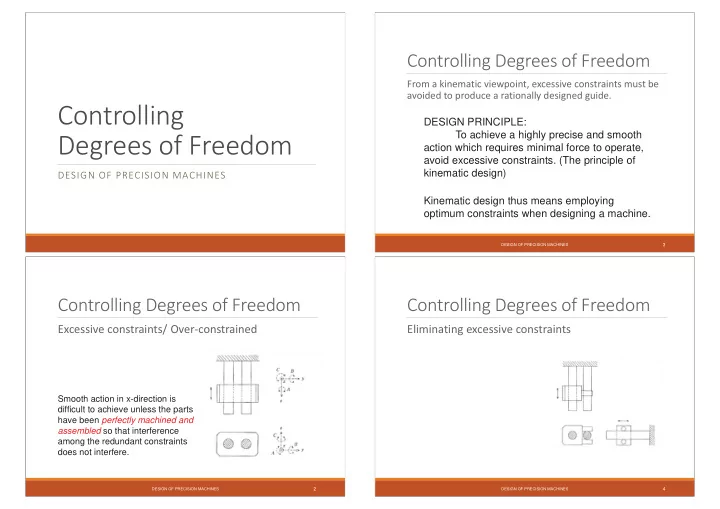
Excessive constraints/ Over-constrained

Smooth action in x-direction is difficult to achieve unless the parts have been perfectly machined and assembled so that interference among the redundant constraints does not interfere.

DESIGN OF PRECISION MACHINES

2

Controlling Degrees of Freedom

From a kinematic viewpoint, excessive constraints must be avoided to produce a rationally designed guide. DESIGN PRINCIPLE: To achieve a highly precise and smooth action which requires minimal force to operate, avoid excessive constraints. (The principle of kinematic design) Kinematic design thus means employing

  • ptimum constraints when designing a machine.

DESIGN OF PRECISION MACHINES

3

Controlling Degrees of Freedom

Eliminating excessive constraints

DESIGN OF PRECISION MACHINES

4

slide-2
SLIDE 2

Controlling Degrees of Freedom

Four column press

Constrained DOFs = 8 x 4 DOFs = 32 DOFs Much of the machining effort is intended to prevent positional over constraint being manifested in the design.

DESIGN OF PRECISION MACHINES

5

Controlling Degrees of Freedom

Alternative concept

With preload Thermal centre Without preload

DESIGN OF PRECISION MACHINES

6

Controlling Degrees of Freedom

Table top and table legs

Bending moments transferred to table top Kinematic mount of table top on table structure

DESIGN OF PRECISION MACHINES

7

Controlling Degrees of Freedom

Exact constrained design For a high level of predictable behaviour and a minimum number of accurate dimensions, exact constrained design is a necessary condition.

DESIGN OF PRECISION MACHINES

8

slide-3
SLIDE 3

Controlling Degrees of Freedom

Elements to constrain degrees of freedom

Symbol for ONE translation Symbol for ONE rotation

DESIGN OF PRECISION MACHINES

9

Controlling Degrees of Freedom

Constraining one translation by contact

A sphere against a flat surface F

  • Constrained DOF

DESIGN OF PRECISION MACHINES

10

Controlling Degrees of Freedom

Contact stress and stiffness with ball support

F

  • Constrained DOF

N/m 10 3 . 4 stiffness contact N/m 10 1360 : ball Steel

3 1 3 1 6 2 6 3 1 2 max ,

F r d dF r F

Hz

  • DESIGN OF PRECISION MACHINES

11

Controlling Degrees of Freedom

Contact stress and stiffness with ball support

F

  • Constrained DOF

DESIGN OF PRECISION MACHINES

12

slide-4
SLIDE 4

Controlling Degrees of Freedom

Damaging steel balls is very easy!

g 20 mm

! N/mm 3000

2

  • Hz
  • DESIGN OF PRECISION MACHINES

13

Controlling Degrees of Freedom

Poor position accuracy in z-direction due to spherical contact area

  • 2

1 ) cos( 2 r

  • r_h

z : error

  • z

ion approximat

2 2

  • DESIGN OF PRECISION MACHINES

14

Controlling Degrees of Freedom

Poor position accuracy in z-direction due to spherical contact area

  • 2

r

  • r_h

z 2 1 ) cos( ) cos( r) (r_h r) r_h ( z : error

  • z

ion approximat

2 2

  • DESIGN OF PRECISION MACHINES

15

Controlling Degrees of Freedom

Constraining ONE translation

DESIGN OF PRECISION MACHINES

16

slide-5
SLIDE 5

Controlling Degrees of Freedom

Constraining ONE translation

DESIGN OF PRECISION MACHINES

17

Controlling Degrees of Freedom

Only one location and direction:

  • no high bending compliance
  • no torsion

DESIGN OF PRECISION MACHINES

18

Controlling Degrees of Freedom

Demo – Folded sheet flexure

DESIGN OF PRECISION MACHINES

19

Controlling Degrees of Freedom

The principle of the “Folded Sheet Flexure”

1 3 3

5 6 3

  • A

G b a EI b a u F c

z z z

DESIGN OF PRECISION MACHINES

20

slide-6
SLIDE 6

Controlling Degrees of Freedom

Constraining ONE rotation

DESIGN OF PRECISION MACHINES

21

Controlling Degrees of Freedom

Constraining ONE rotation

torsionally stiff body torsionally stiff body torsionall

DESIGN OF PRECISION MACHINES

22

Controlling Degrees of Freedom

Constraining ONE rotation

DESIGN OF PRECISION MACHINES

23

Controlling Degrees of Freedom

Constraining ONE rotation

Be careful with intermediate elements!

  • buckling
  • resonances
  • fatigue

DESIGN OF PRECISION MACHINES

24

slide-7
SLIDE 7

Controlling Degrees of Freedom

Constraining ONE rotation

DESIGN OF PRECISION MACHINES

25

Controlling Degrees of Freedom

Constraining TWO translations

DESIGN OF PRECISION MACHINES

26

Controlling Degrees of Freedom

Constraining TWO translations

More robust embodiment!!!

DESIGN OF PRECISION MACHINES

27

Controlling Degrees of Freedom

Constraining one translation and one rotation

about the same axis…. about perpendicular axes...

DESIGN OF PRECISION MACHINES

28

slide-8
SLIDE 8

Controlling Degrees of Freedom

Constraining two translations and one rotation in one plane

DESIGN OF PRECISION MACHINES

29

Controlling Degrees of Freedom

Constraining two rotations

DESIGN OF PRECISION MACHINES

30

Controlling Degrees of Freedom

Constraining three translations

DESIGN OF PRECISION MACHINES

31

Controlling Degrees of Freedom

Constraining three translations

Example: elastic ball joint with coinciding poles

DESIGN OF PRECISION MACHINES

32

slide-9
SLIDE 9

Controlling Degrees of Freedom

Constraining three DOFs

DESIGN OF PRECISION MACHINES

33

Controlling Degrees of Freedom

Constraining three DOFs using folded sheet flexures

DESIGN OF PRECISION MACHINES

34

Controlling Degrees of Freedom

Constraining three DOFs using folded sheet flexures

DESIGN OF PRECISION MACHINES

35

Controlling Degrees of Freedom

Constraining three rotations

DESIGN OF PRECISION MACHINES

36

slide-10
SLIDE 10

Controlling Degrees of Freedom

Constraining two translations and two rotations

DESIGN OF PRECISION MACHINES

37

Controlling Degrees of Freedom

Two degrees of freedom (translations) in one plane

DESIGN OF PRECISION MACHINES

38

Controlling Degrees of Freedom

Free one DOF: translation

Correct parallel guiding

DESIGN OF PRECISION MACHINES

39

Controlling Degrees of Freedom

Free one DOF: rotation

DESIGN OF PRECISION MACHINES

40

slide-11
SLIDE 11

Controlling Degrees of Freedom

Free one DOF: rotation

Example: cross spring pivot

centre line leaf spring

DESIGN OF PRECISION MACHINES

41

Controlling Degrees of Freedom

Constraining 6 DOF: kinematic mount

DESIGN OF PRECISION MACHINES

42

Controlling Degrees of Freedom

Constraining 6 DOFs with 2 sheet flexures?

DESIGN OF PRECISION MACHINES

43

Controlling Degrees of Freedom

Constraining 6 DOFs with 2 sheet flexures?

translation is over-constrained, rotation free rotation free

DESIGN OF PRECISION MACHINES

44

slide-12
SLIDE 12

Controlling Degrees of Freedom

Examples of controlling DOFs

DESIGN OF PRECISION MACHINES

45

Controlling Degrees of Freedom

Ball joint with intermediate body

DESIGN OF PRECISION MACHINES

46

Controlling Degrees of Freedom

Ball joint with intermediate body

Play-free mounting of the ball hinge cup

DESIGN OF PRECISION MACHINES

47

Controlling Degrees of Freedom

Ball hinge based on “wire flexures”

Friction release is uncontrolled Flexure ball hinge lacks hysteresis

DESIGN OF PRECISION MACHINES

48

slide-13
SLIDE 13

Controlling Degrees of Freedom

Linking shafts which are not aligned precisely

  • Transferring ONE DOF: a rotation

DESIGN OF PRECISION MACHINES

49

Controlling Degrees of Freedom

Linking shafts which are not aligned precisely

  • Transferring ONE DOF: a rotation

Coupling with single thin bar

DESIGN OF PRECISION MACHINES

50

Controlling Degrees of Freedom

Linking shafts which are not aligned precisely

  • Transferring ONE DOF: a rotation

Angular precision dependent

  • n alignment errors:

DESIGN OF PRECISION MACHINES

51

Controlling Degrees of Freedom

Flexible coupling with 3 thin bars

(universal joint)

DESIGN OF PRECISION MACHINES

52

slide-14
SLIDE 14

Controlling Degrees of Freedom

Flexible coupling with 2 times 3 thin bars

DESIGN OF PRECISION MACHINES

53

Controlling Degrees of Freedom

Torsionally stiff coupling based on elastic elements equivalent to “Oldham coupling”

Courtesy Huco

in

  • ut
  • ut

DESIGN OF PRECISION MACHINES

54

Controlling Degrees of Freedom

Detailed design “Koster-coupling”

DESIGN OF PRECISION MACHINES

55

Controlling Degrees of Freedom

Torsionally stiff coupling based on folded sheet flexures

DESIGN OF PRECISION MACHINES

56

slide-15
SLIDE 15

Controlling Degrees of Freedom

Transmitter of information on one angle Version suitable for high rotational velocities

DESIGN OF PRECISION MACHINES

57

Controlling Degrees of Freedom

Constraining axial displacement without using material at the centre line

DESIGN OF PRECISION MACHINES

58

Controlling Degrees of Freedom

Point of support should be in neutral plane of membrane

DESIGN OF PRECISION MACHINES

59

Controlling Degrees of Freedom

Self-centering driver

Compare to a splined-shaft...

  • shafts remain centered in relation to another
  • every point of contact has equal load

DESIGN OF PRECISION MACHINES

60

slide-16
SLIDE 16

Concept of Thermal Centre (TC)

DESIGN OF PRECISION MACHINES

61

Controlling Degrees of Freedom

The Concept of Thermal Centre (TC)

Using symmetry to position the thermal centre in the object centre

DESIGN OF PRECISION MACHINES

62

Controlling Degrees of Freedom

The body is free to expand without affecting the centre position

DESIGN OF PRECISION MACHINES

63

Controlling Degrees of Freedom

Constraining a centre line

Instant centre of rotation does not coincide with the thermal centre

DESIGN OF PRECISION MACHINES

64

slide-17
SLIDE 17

Controlling Degrees of Freedom

Constraining a centre line with folded sheet flexures

Advantages:

  • no rotation
  • stiffer

Lower axial stiffness

DESIGN OF PRECISION MACHINES

65

DESIGN OF PRECISION MACHINES

66

Example: Thermal centre laser-welding head

Controlling Degrees of Freedom

Three balls in V-grooves: kinematic support

Use radially stiff bodies to minimise virtual play

DESIGN OF PRECISION MACHINES

67

Controlling Degrees of Freedom

V-groove coupling designed to avoid expansion induced hysteresis Cross-section A-A Cross-section B-B

DESIGN OF PRECISION MACHINES

68

slide-18
SLIDE 18

Controlling Degrees of Freedom

V-groove coupling designed to avoid expansion induced hysteresis: alternative embodiment

DESIGN OF PRECISION MACHINES

69

Controlling Degrees of Freedom

Kinematic connection (not dismountable)

Elastic version (not dismountable)

DESIGN OF PRECISION MACHINES

70

Controlling Degrees of Freedom

Nest of Springs

DESIGN OF PRECISION MACHINES

71

Controlling Degrees of Freedom

The stiffness of a slanted truss

  • 2

cos '

  • c

c

DESIGN OF PRECISION MACHINES

72

slide-19
SLIDE 19

Controlling Degrees of Freedom

The stiffness of a slanted truss

  • r

r rad

c c c

  • 2

2

cos sin

DESIGN OF PRECISION MACHINES

73

Controlling Degrees of Freedom

Radial stiffness of a nest of springs

n times cr (ct = 0)

  • r

r rad

c n c n c

  • 2

cos sin 2

2 2

  • DESIGN OF PRECISION MACHINES

74

Controlling Degrees of Freedom

Example of a nest of springs: ball bearing

ball v

c n c 2

  • DESIGN OF PRECISION MACHINES

75

Controlling Degrees of Freedom

Introducing an object into a nest of springs

Perfect nest of springs Perfect cylinder in a perfect nest of springs Non-round cylinder in a perfect nest of springs. The point that coincides with M is the centre of gravity MC

  • f the cylinder circumference

DESIGN OF PRECISION MACHINES

76

slide-20
SLIDE 20

Controlling Degrees of Freedom

Radial stiffness of a nest of springs

n times cr and ct

t r r

c n c n c

  • 2

2

DESIGN OF PRECISION MACHINES

77

Controlling Degrees of Freedom

Nest of springs in a glass holder of an old fashioned oil lamp

DESIGN OF PRECISION MACHINES

78

Controlling Degrees of Freedom

Lens mount based on a nest-of-springs-suspension

DESIGN OF PRECISION MACHINES

79

Controlling Degrees of Freedom

In conclusion:

Why “Exactly Constrained” Designs?

  • Minimum number of accurate tolerances
  • No “transfer” of deformations
  • Predictable thermal behavior
  • Predictable force paths

DESIGN OF PRECISION MACHINES

80

slide-21
SLIDE 21

Fine manipulation and adjustment

DESIGN OF PRECISION MACHINES

81

  • y

x e e a u u u 1 1 1

3 2 1

  • x

y

e e a

1

u

2

u

3

u

In-plane fine manipulation with adjustment procedure

  • 3

2 1

2 1 2 1 2 1 2 1 2 2 1 u u u e e e a e a y x

  • DESIGN OF PRECISION MACHINES

82

  • y

x e u u u 1 1 1

3 2 1

e

1

u

2

u

  • x

y

3

u

In-plane fine manipulation with limited adjustment procedure

  • 3

2 1

1 1 1 1 u u u e e y x

  • DESIGN OF PRECISION MACHINES

83

  • x

y

2

u

1

u

3

u

r

  • y

x r u u u 1 1

3 2 1

b a l l

  • l

l l

In-plane fine manipulation with independent adjustments (1/2)

DESIGN OF PRECISION MACHINES

84

slide-22
SLIDE 22
  • x

y

2

u

1

u

3

u

r

  • y

x r u u u 1 1

3 2 1

l l l l

  • l

In-plane fine manipulation with independent adjustments (2/2)

DESIGN OF PRECISION MACHINES

85

  • y

x a a a u u u 1 2 3 2 1 2 3 2 1

3 2 1

  • x

y

1

u

2

u

3

u

120º 120º a

In-plane fine manipulation for maximum stiffness

DESIGN OF PRECISION MACHINES

86

Accuracy of an operation: closeness of the agreement between the actual value resulting from an operation and a target value of the

  • quantity. Accuracy is a qualitative description.

Uncertainty of an operation: parameter, associated with the result

  • f an operation that characterizes the dispersion of the values that

could reasonably be attributed to the quantity. Resolution: smallest difference between indications of displaying device that can be meaningfully distinguished. Repeatability (of results of operations): closeness of the agreement between the results of successive operations of the same quantity carried out under the same conditions. Reproducibility: closeness of the agreement between the results of

  • perations of the same quantity carried out under changed

conditions.

  • P. Schellekens et al., Design for Precision: Current Status and Trends, CIRP 1998

DESIGN OF PRECISION MACHINES

87

Adjusting 6 DOFs (1/2)

Adjustment sequence: 1) position x,y,z 2) angles ,,

x y

  • z
  • u1

u2 u3 u4 u5 u6 r r r

  • z

y x r r r u u u u u u 1 1 1 1 1 1

6 5 4 3 2 1 DESIGN OF PRECISION MACHINES

88

slide-23
SLIDE 23

Adjusting 6 DOFs (2/2)

3 orthogonal 2 DOF adjustments

  • z

y x r r r u u u u u u 1 1 1

6 5 4 3 2 1

y

  • x
  • z
  • u2

u5 r

P

DESIGN OF PRECISION MACHINES

89

y

  • x
  • z
  • u1

u2 u4 u5 u6 2r 2r 2r

  • z

y x r r r r r r u u u u u u 1 1 1 1 1 1

6 5 4 3 2 1

P E,A,l u3

Equal stiffness in all directions

l EA c 2

  • 2

2 r l EA k

DESIGN OF PRECISION MACHINES

90

6-DOF Stewart platform using piezo motors

  • 6-DOF motion mechanism is based on elastic hinges
  • Accuracy sub-micron
  • High stiffness due to parallel actuator design

DESIGN OF PRECISION MACHINES

91

End of Chapter!