
SLIDE 1
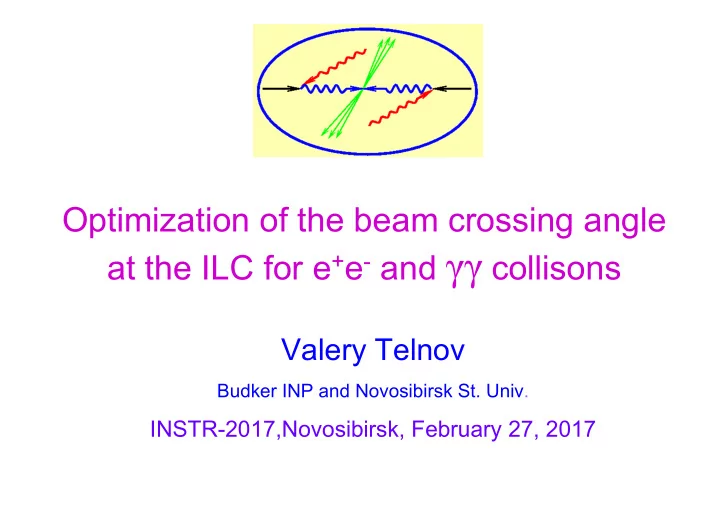
Optimization of the beam crossing angle at the ILC for e+e- and γγ collisons
Valery Telnov
Budker INP and Novosibirsk St. Univ.
Contents Introduction The X(750) bump as a god signal to remind - - PowerPoint PPT Presentation
Optimization of the beam crossing angle at the ILC for e + e - and collisons Valery Telnov Budker INP and Novosibirsk St. Univ. INSTR-2017,Novosibirsk, February 27, 2017 Contents Introduction The X(750) bump as a god signal to
Budker INP and Novosibirsk St. Univ.
2
3
Photon colliders
4
αc ~25 mrad
b~γσy~1 mm
5
ILC(500)
6 Gamma-gamma workshop LBL, 1994
NLC TESLA CDR γγ at JLC TESLA TDR γγ at DESY γγ NLC PLC 2005 Photon colliders were suggested in 1981 and since ~1990 are considered as a natural part of all linear collider projects.
7
L=31 km 2E=500 GeV
2E=250-500 GeV, upgradable to 1000 GeV
8
9
Гtot, Z tagging
In e+e- In γγ
charge particles (even with M>2E0), therefore this process is most sensitive to new physics! In γγ collisions the Г(H→γγ) width can be measured with statistics ≈ 90 times higher than in e+e- collisions. This is the most important argument for the photon collider . However, e+e- beams are much better for Higgs study (due to Z tagging). Therefore PLC has sense only in combination with e+e-: parallel work or second stage.
10
ILC uses the same technology as TESLA which published TDR in 2001, all new developments were focused on the cost reduction: only one IP,
There was suggestion (Sugawara) in 2009 to build PLC for the Higgs study before e+e-, but it was not supported because e+e- are much better for H study. So, the PLC is considered as an option which will be realized either after finishing e+e- program (in >20 years) or earlier, if strong physics case. It is OK, there is only one problem for now: the ILC design should be compatible with the PLC in order to have possibility
The most important requirement: the crossing angle should be about 25 mrad for PLC, while it is now 14 mrad for e+e-. This problem is well known but not solved yet because the most important problem for the ILC management is the approval of the ILC project in the present baseline (cheapest) version. However, in 2015 the HEP community was excited by the unexpected diphoton signal of new physics at LHC, which was the best possible argument for the photon collider.
11
On June 9 Lyn Evans has written in LC Newsline: "On the scientific side, there was much discussion of the possible sighting
recommended that the possible option of running the ILC as a gamma- gamma collider at 1 TeV as well as an e+e–collider be strongly
Yes, now it requires minor modification, but if to do nothing, later such modification (crossing angle) will be very difficult. The god likes to speak with people indirectly and this diphoton bump was just a gentle reminding to the LCC and LCB that it is time to correct the ILC design in order to make it compatible with the photon collider. In 2015 two detector at LHC have observed the (fake) diphoton peak at Wγγ≈750 GeV which caused a lot of excitement in HEP community (> 500 papers).
12
αc ~25 mrad
b~γσy~1 mm
13
The additional deflection ~2-4 mrad adds the detector field Low energy electron are deflected in the field of the opposing e-beam Angles of disrupted electrons after Compton scattering and interaction with
14
2E0=200 GeV 2E0=500 GeV With account of tails the save beam sizes are larger by about 20 %.
15
Principle design of the superconducting quad (B.Parker), only coils are shown (two quads with opposite direction of the field inside each
X (mm) Y (mm)
10 20 30
10 20 30 For compensation Gin = 160 T/m at Io = 767 A Gout = -20 T/m at Io = 517 A for Geff = 140 T/m Lmag = 2.200 m Lc oi l = 2.228 m
So, the required crossing andle for PLC is about 25 mrad It is larger than in e+e- case (14 mrad) due to disruption angles and lower energies. (At present warm hybrid quads are considered as well)
16
additional angle is 5.5mrad and detector needs to be moved by about 4.2m as well as 1.4 km of beam lines + separate beam dump, too big job!
A.Seryi, LCWS06 1400 m
Much more attractive would be the same angle for e+e- and γγ.
17
(V.Telnov, physics/0507134)
as a function of the crossing angle (full simulation) At 25 mrad the loss of luminosity is less than 5% and at 20 mrad the effect is negligible. This effect strongly depends on crossing angle ∆ε~(Bαc)5 The crossing angle somewhat smaller than 25 mrad would be OK both for ILC(e+e-) and PLC.
18
The minimum energy after n Compton scatterings
2 4 2 4 min
c T
2
T e
Low energy electrons after multiple Compton scattering are deflected by opposing electron beam, the disruption angle So, for the fixed collision probability (p) and laser wavelength the minimum Emin is reached at the maximum collider energy (because σc is smaller for larger x, see Fig). After the first scattering the Compton cross section increases from The collision probability at the CP is
sc
where
sc c
c x
up to and the number of multiple scattering
T c
min
d z c z
2 4
19
min 0/
d z z c
So, the disruption angle while the luminosity
2 2 1.15 2
p x y z z
(because , and )
1 , 1
p
k e p
y y y z
(for p~1)
depends
wavelength
Ways to 20 mrad from present 25 mrad. In the case of αc=25 mrad ½ is determined by quad’s sizes and ½ by the disruption angle. In order to reduce αc from 25 to 20 mrad we have to reduce θd by 5 mrad or 12.5/7.5=1.67 times. For the fixed laser wavelength λ=1 µm one can 1) decrease p by a factor of (1.67)2=2.8, from p=1 to 0.358, then the luminosity drops by a factor of 4.4 which is not acceptable. 2) increase σz 2.8 times, which leads to the decrease of L by a factor of 1.7, and requires approximately 3 time larger laser flash energy. Another way is the increase of the laser wavelength! In this way one can reduce the disruption angle without any decrease of the luminosity.
.
20
For x>4.8 the luminosity in the high energy lum. peak decreases due to e+e- pair creation in collision of laser and high energy photons at the conversion point. For the maximum collider energy E0 the optimum laser wave length (x=4.8) is
The maximum energy of photons after the Compton scattering
max 2 4
So, λ=1 µm is good only for 2E0<500-600 GeV, while the updated ILC energy could reach 2E0=1 TeV or even higher. If the PLC starts operation when ILC already has 2E0=1 TeV, the it has big sense to consider λ=2 µm from the very beginning. This choice has many other advantages, see below.
21
λ, μm 1 1.5 2 H (125) 210 235 255 top(360) 485 520 550 The energy 2E0 required for the study of the H(125) and top threshold Here Wγγ corresponds to the peak of lum. spectra 21% 13.4% In order to have at the PLC with λ=2 µm the same energy reach as with λ=1 µm with 2E0=500 GeV one need 2E0=565 GeV (or 13% higher only).
22
c d z
For 2E0=500 and λ=1 µm x=4.75 and σc/σ0=0.705 For 2E0=500 and λ=2 µm x=2.37 and σc/σ0=1.1 therefore the disruption angle with λ=2 µm is smaller by a factor of 1.77 (we needed 1.67 in order to reach αc=20 mrad.) For 2E0=1000 and λ=2 µm x=4.75 and σc/σ0=0.705 and θd will be =1.41 times smaller than for 2E0=500 and λ=1 µm (the worst case with θd=12.5 mrad). The factor 1.41 is somewhat smaller than needed 1.77, but present 12.5 mrad has two contributions: a) from beam-beam collisions which is proportional to 1/sqrt(Emin) b) deflection in the solenoid field which is proportional to 1/Emin. so, the decrease θd by a factor of may be sufficient.
2 2
23
2E0=500 GeV, λ=1 μm 2E0=1000 GeV, λ=2 μm The problem is solved, 20 mrad crossing angle is possible.
(If necessary, some additional reduction of θd can be obtained by some increasing of the σz without substantial loss of luminosity.)
24
25
The laser flash energy for λ=2 μm for various nonlinear parameter ξ2 and conversion probabilities.
Here the parameter
characterizes nonlinear effects in Compton scat- tering and should be kept small (0.15-0.3), because
2
m
The required flash energy is larger than at λ=1 μm by about 20%.
2 2 2 2 2 2 2 2
e
26
(just reminding, all reported dozen times and published)
27
28