Constructing density. the marker function 4. There are several - - PowerPoint PPT Presentation

constructing
SMART_READER_LITE
LIVE PREVIEW

Constructing density. the marker function 4. There are several - - PowerPoint PPT Presentation

1. In this segment we continue to develop a front tracking method, based on advecting connected DNS of Multiphase Flows Simple Front Tracking Direct Numerical marker points. Simulations of Multiphase Flows-5 Advecting the Marker


slide-1
SLIDE 1

DNS of Multiphase Flows — Simple Front Tracking

Direct Numerical Simulations of Multiphase Flows-5


Advecting the Marker Function using Front Tracking (2 of 2)

Gretar Tryggvason

  • 1. In this segment we continue to develop a front tracking method, based on advecting connected

marker points.

DNS of Multiphase Flows — Simple Front Tracking In the last lecture we introduced a simple front tracking method and showed how to:

  • Set up a front consisting of connected marker points
  • Identify the points on the fixed grid that are closest to a

given front point

  • Interpolate the velocities on the fixed grid to the front
  • Add and delete points to the front

Here we will:

  • Construct a marker function from the new location of

the front

  • Replace the density advection used in the first version
  • f our code with the front tracking
  • 2. In the last lecture we started to develop a simple front tracking method, using ordered marker points.

We showed how to set up the front for a closed interface, representing a bubble or a drop. We found a way to identify which points on the fixed grid are closest to a given front point, and we developed a strategy to interpolate the velocities on the fixed grid to the front and move the interface points once we had their velocities. We also introduced a simple way to add and delete marker points as the distance between them changes. Here we will construct a marker function from the new location of the front and then update the code we wrote for variable density flow by replacing the density advection scheme with the front tracking.

DNS of Multiphase Flows — Simple Front Tracking

Constructing the marker function

  • 3. Advecting the density by moving the points that mark the position of the interface between regions of

different densities is a two-step process. First we move the marker points by the fluid velocity, interpolated from the grid, and then we construct the marker field on the grid, from the new location of the points. In the last lecture we moved the points and here we will create the marker and set the density.

slide-2
SLIDE 2

DNS of Multiphase Flows — Simple Front Tracking There are several ways to construct a marker function given the location of the interface Generally the front moves less than a grid spacing so we

  • nly need to update points close to the interface

Usually we want the marker function to transition from one value to the other in a way that depends on the distance to the interface The most straightforward approach is to loop over the interface points, find the closest points on the fixed grid and set their values depending on which side of the front it is and how far

  • 4. There are several ways to construct a marker function given the location of the interface, but in all

cases the easiest way is to loop over the interface points, find the closest points on the fixed grid and set their values, depending on whether they are on the right or left side of the front. Usually the front moves less than one grid spacing so we only need to update points close to the interface. We also generally want the marker function to transition from one value to the other in a smooth way that depends on the distance to the interface.

DNS of Multiphase Flows — Simple Front Tracking To determine how the marker function value depends on the exact location of the interface and the distance to each grid point it is necessary to:

  • Determine which part of the interface is closest to

a given point on the fixed grid,

  • Determine the distance from the interface to each

point on the fixed grid,

  • Decide how the marker value depends on the

distance to the interface We first look at the last issue

  • 5. To determine how the marker function value depends on the exact location of the interface and the

distance to each grid point, we need to determine which part of the interface is closest to a given point

  • n the fixed grid, find the distance from the interface to each point on the fixed grid, and decide how

the marker value depends on the distance to the interface. We first look at the last issue.

DNS of Multiphase Flows — Simple Front Tracking To determine how the marker function value depends on the exact location of the interface and the distance to each grid point we first consider a one-dimensional grid: If the front is in the middle, between two grid points, we can set the value to 0 on one side and 1 on the other If the front is exactly at a grid point, it seems reasonable to set the indicator at that point to 0.5 and 0 and 1 at the points

  • n either side

Same as the first case but shifted to the right j-1 j j+1 j-1 j j+1 j-1 j j+1

  • 6. The strategy that we use here is to simply set the markers at the grid points of the fixed grid based on

their distance from the interface. To decide how the marker value depends on the distance, we start with a one-dimensional example. If the front is located exactly in the middle between two grid points, say j-1 and j then it seems reasonable that the marker value at the grid point on one side is zero and the value at the point on the other side is one. Similarly, if the front is located exactly at grid point j, then we set the value there equal to a half and the values at j-1 to zero and at j+1 to one. If the front is moved further to the right, then eventually it is half way between j and j+1 and we treat it exactly the same as in the first case, except shifted one grid point to the right.

slide-3
SLIDE 3

DNS of Multiphase Flows — Simple Front Tracking For front at other locations we interpolate. If the signed distance

  • f the front from grid point j is d, where d < 0 on the left and d > 0
  • n the right, and is the distance between the grid points:

j-1 j j+1 j-1 j j+1 Find the signed distance to grid point j j-1 j j+1 ∆x d

dj = xf − xj

χj = 8 < : dj < −∆x/2 1/2 + dj/∆x |dj| < ∆x/2 1 dj > ∆x/2

Front points outside the vertical lines do not affect the value at grid point j Then interpolate : ∆x

dj

  • 7. If the front is neither half way between two grid points nor exactly at a grid point, the simplest

approach is to interpolate linearly between the two cases. Thus, if d_j is the distance between the front point and grid point j and delta x is the grid spacing, then the value of the marker at grid point j is zero if d_j is less than negative half the grid spacing. If d_j is between negative delta x over 2 and positive delta x over 2 then the value is half plus d_j over delta x, and if d_j is greater than delta x over 2 then the marker function is equal to 1. Assuming that the motion of the front is always less than a grid spacing, then we need not concern us with points further away.

DNS of Multiphase Flows — Simple Front Tracking Since we need the normal to the interface, we will work with the line segment between two front points, instead of the points. In 2D we need to find the closest front point and set the marker based on the perpendicular distance First we define the front point as the mid point of the segment Then we find the distance from the front point to each of the four closest grid points

xf = 1 2(xl + xl+1)

d1 = s✓xf − xi,j ∆x ◆2 + ✓yf − yi,j ∆y ◆2 ✓ ◆ ✓ ◆

d1 d2 d3 d4 : ∆x ∆y

) (i + 1, j) ( ) (i + 1, j + 1) (i, j + 1) : (i, j) (

xl xl+1

Note that we use scaled distance since can be different from : ∆x ∆y

  • 8. In two dimensions we need first of all to determine which part of the front is closest to a given grid

point and then find the perpendicular distance to the interface. To make the computations of the normal as simple as possible, we will work with the segment between two front points and define the front point as the average of the end points. Since what matters when we set the values of the grid points is the relative distance compared to the grid size and we allow the grid spacing in x and y to be uneven, we will scale x and y distances separately by delta x and delta y. Thus, the relative distance from the red point on the front to the grid point in the lover left corner (i,j) is the square root of the square of x_f minus x(i,j) divided by delta x, plus the square of y_f minus y(i,j) divided by delta y. The distances to the

  • ther grid points are found in the same way.

DNS of Multiphase Flows — Simple Front Tracking To find the perpendicular distance to each of the nearest grid points, we first find the normal to the front segment between front point l and l +1.

∆sf = p (xl+1 − xl)2 + (yl+1 − yl)2 : ∆xf = xl+1 − xl ∆yf = yl+1 − yl nf = (∆yf, −∆xf)/∆sf = (nx, ny)

∆xf ∆yf

nf

xl+1 xl

(i, j)

The x and y separation, the length

  • f the segment, and the normal are:

The scaled normal distance is then given by the dot product of the distance between the grid point and the front point and the normal vector

✓ ◆ ✓ ◆ dn1 = ✓xf − xi,j ∆x ◆ nx + ✓yf − yi,j ∆y ◆ ny 8

d1

∆sf dn1

  • 9. To find the perpendicular distance from the front to each of the nearest grid points, we first find the

normal to the front segment between front point i and i+1. Defining delta x_f and delta y_f as the differences between the endpoints of the segment, as shown in the slide, the normal is given by delta y-f comma minus delta x_f, divided by the length of the line segments, computed as square root of delta x_f squared plus delta y_f squared. The perpendicular relative distance between a given front point and the lower left hand corner point on the fixed grid (or point i,j), or dn-1, is then equal to the projection of the distance vector onto the normal, or x_f minus x(i,j), divided by delta x, times the x component of the normal plus y_f minus y(i,j) divided by delta y, times the y component of the normal.

slide-4
SLIDE 4

DNS of Multiphase Flows — Simple Front Tracking Although we use the front point closest to the given grid point, we set the marker based on the perpendicular distance : ∆x ∆y

: (i, j) (

xl xl+1

In the actual code we update the marker only at grid points close to the interface, since points far away are not affected by the interface motion The other three grid points are update in the same way

dn1 χi,j = 8 < : dn1 < −1/2 1/2 + dn1 |dn1| < 1/2 1 dn1 > 1/2 ✓ ◆ ✓ ◆ dn1 = ✓xf − xi,j ∆x ◆ nx + ✓yf − yi,j ∆y ◆ ny 8

The perpendicular distance is: And the marker value is:

  • 10. Notice that the perpendicular distance is a signed quantity that is negative on one side of the

interface and positive on the other. To update the value of the marker at each grid point we therefore set the marker to zero if the scaled distance is minus a half or less, one if the distance is more than a half, and if it is in between minus a half and plus a half, we interpolate and set it equal to half plus the

  • distance. Here we show how we set the marker value for the lower left corner of the grid cell. The values

for the other three grid points are set in the same way.

DNS of Multiphase Flows — Simple Front Tracking

%-------------- Update the marker function --------------------- d(2:nx+1,2:ny+1)=2; for l=2:Nf+1 nfx=-(yf(l+1)-yf(l))/dx; nfy=(xf(l+1)-xf(l))/dy; % Normal vector ds=sqrt(nfx*nfx+nfy*nfy); nfx=nfx/ds; nfy=nfy/ds; xfront=0.5*(xf(l)+xf(l+1)); yfront=0.5*(yf(l)+yf(l+1)); ip=floor((xfront+0.5*dx)/dx)+1; jp=floor((yfront+0.5*dy)/dy)+1; d1=sqrt(((xfront- x(ip))/dx)^2+((yfront- y(jp))/dy)^2); d2=sqrt(((xfront-x(ip+1))/dx)^2+((yfront- y(jp))/dy)^2); d3=sqrt(((xfront-x(ip+1))/dx)^2+((yfront-y(jp+1))/dy)^2); d4=sqrt(((xfront- x(ip))/dx)^2+((yfront-y(jp+1))/dy)^2); if d1<d(ip,jp), d(ip,jp)=d1;... dn1=(x(ip)- xfront)*nfx/dx+(y(jp)- yfront)*nfy/dy; chi(ip,jp)= 0.5*(1.0+sign(dn1)); if abs(dn1)<0.5, chi(ip,jp)= 0.5+dn1; end; end if d2<d(ip+1,jp), d(ip+1,jp)=d2;... dn2=(x(ip+1)-xfront)*nfx/dx+(y(jp)- yfront)*nfy/dy; chi(ip+1,jp)= 0.5*(1.0+sign(dn2)); if abs(dn2)<0.5, chi(ip+1,jp)= 0.5+dn2; end; end if d3<d(ip+1,jp+1), d(ip+1,jp+1)=d3;... dn3=(x(ip+1)-xfront)*nfx/dx+(y(jp+1)-yfront)*nfy/dy; chi(ip+1,jp+1)=0.5*(1.0+sign(dn3)); if abs(dn3)<0.5, chi(ip+1,jp+1)=0.5+dn3; end; end if d4<d(ip,jp+1), d(ip,jp+1)=d4;... dn4=(x(ip)- xfront)*nfx/dx+(y(jp+1)-yfront)*nfy/dy; chi(ip,jp+1)= 0.5*(1.0+sign(dn4)); if abs(dn4)<0.5, chi(ip,jp+1)= 0.5+dn4; end; end end

In the actual code, we loop over the front points and identify close grid points.

  • 1. First define a distance vector for all the

grid points and initialize it by some value larger than twice the grid spacing.

  • 2. Within the loop find the grid points close

to a given front point, defined as the average of the endpoints of a given segment

  • 3. Compute the distance between the front

point and each grid point

  • 4. For each grid point we check if the

distance from the front point is smaller than what has already been found. If it is smaller we first set the marker value to either zero or one, depending on the sign

  • f the perpendicular distance. If the

absolute value of the scaled perpendicular distance is less than a half, we interpolate.

  • 11. A code to update the marker function next to the front is all contained in one loop over the front
  • points. First we set the scaled distance from the front equal to a large value for all points of the fixed
  • grid. This is simply an initial guess that will be updated. In the second step we find the normal vector and

the midpoint of the front element. Then we compute the distance to the four grid points surrounding the front point. For each grid point we check if the distance from the front point is smaller than what has already been found. If it is smaller, we first set the marker value to either zero or one, depending on the sign of the perpendicular distance, and if the absolute value of the scaled perpendicular distance is less than a half, we interpolate.

DNS of Multiphase Flows — Simple Front Tracking Once we have found the values of the marker function, the various material properties are set as functions of the

  • marker. Here we assume

a simple linear dependency and set the density by: In principle we only need to update the values near the interface but here we loop over the whole domain to simplify the programming. Thus, we can set:

for i=2:nx+1,for j=2:ny+1 r(i,j)=rho1+(rho2-rho1)*xi(i,j); end,end

χ = ⇢ 1 in fluid 1 0 in fluid 2 ⇢ − ρ = χρ1 + (1 − χ)ρ2 ⇢ ρ = ⇢ ρ1 in fluid 1 ρ2 in fluid 2

We have We need The code

  • 12. Once the marker function has been constructed from the location of the front, we can set the various

material properties as functions of the marker values. Here we assume a simple linear dependency and set the density as the marker function times density in fluid one, where the marker is one, plus one minus the marker times the density in fluid 2, where the marker is zero. In principle we only need to update the values near the interface but here we loop over the whole domain to simplify the programming. If we use the density as the marker function, then we obviously can skip this step.

slide-5
SLIDE 5

DNS of Multiphase Flows — Simple Front Tracking

The Code

  • 13. We can now modify our code and replace the simple advection equation for the density by the front

tracking approach.

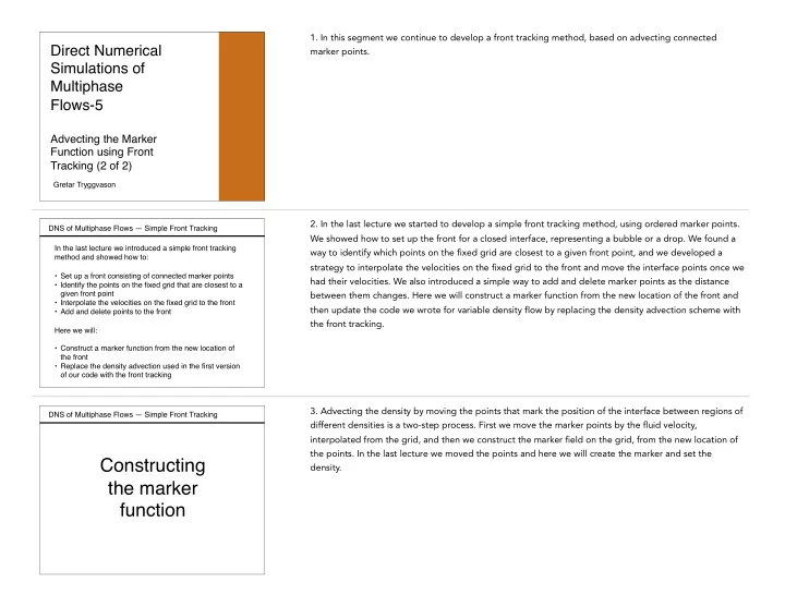
DNS of Multiphase Flows — Simple Front Tracking We are now ready to replace the simple advection of the density used in the original flow solver with the front tracking code. The new parts are:

  • The setup of the front
  • The interpolation of the grid velocity to the front and

the advection of the front

  • The adding and deletion of points to keep the

resolution reasonably uniform

  • The construction of a marker function from the

location of the front

  • Update of the material properties at the new time
  • 14. To do so we need to add four new parts. The first is the setup or the initialization of the front; then

we need to interpolate the grid velocity to the front and advect the front; and after that we construct the marker function from the location of the front. Finally we need to add and delete points at the front to keep the resolution reasonably uniform.

DNS of Multiphase Flows — Simple Front Tracking

Code added for the front tracking

%=============================================================== % CodeC2-frt.m % A very simple Navier-Stokes solver for a drop falling in a % rectangular box, using a conservative form of the equations. % A first-order explicit projection method and centered in space % discretizationa are used. The marker function is advected by % Tront Tracking. Last edited 7/6/2016 %=============================================================== Lx=1.0;Ly=1.0;gx=0.0;gy=-100.0; rho1=1.0; rho2=2.0; % Domain size and m0=0.01; % physical variables unorth=0;usouth=0;veast=0;vwest=0;time=0.0; rad=0.15;xc=0.5;yc=0.7; % Initial drop size and location %-------------------- Numerical variables ---------------------- nx=32;ny=32;dt=0.00125;nstep=400; maxit=200;maxError=0.001;beta=1.5; Nf=100; %-------------------- Zero various arrys ----------------------- u=zeros(nx+1,ny+2); v=zeros(nx+2,ny+1); p=zeros(nx+2,ny+2); ut=zeros(nx+1,ny+2); vt=zeros(nx+2,ny+1); tmp1=zeros(nx+2,ny+2); uu=zeros(nx+1,ny+1); vv=zeros(nx+1,ny+1); tmp2=zeros(nx+2,ny+2); r=zeros(nx+2,ny+2); chi=zeros(nx+2,ny+2); xf=zeros(1,Nf+2); yf=zeros(1,Nf+2); uf=zeros(1,Nf+2); vf=zeros(1,Nf+2); dx=Lx/nx;dy=Ly/ny; % Set the grid for i=1:nx+2; x(i)=dx*(i-1.5);end; for j=1:ny+2; y(j)=dy*(j-1.5);end; %-------------------- Initial Conditions ----------------------- r=zeros(nx+2,ny+2)+rho1; % Set density for i=2:nx+1,for j=2:ny+1; % for the domain and the drop if((x(i)-xc)^2+(y(j)-yc)^2 <rad^2),r(i,j)=rho2;chi(i,j)=1.0;end, end,end for l=1:Nf+2, xf(l)=xc-rad*sin(2.0*pi*(l-1)/(Nf)); % Initialize yf(l)=yc+rad*cos(2.0*pi*(l-1)/(Nf));end % the Front hold off,contour(x,y,flipud(rot90(chi))),axis equal,axis([0 Lx 0 Ly]); hold on;plot(xf(1:Nf),yf(1:Nf),'k','linewidth',3);pause(0.01) %---------------------- START TIME LOOP ------------------------ for is=1:nstep,is %---------------------- Advect the Front ----------------------- for l=2:Nf+1 % Interpolate the Front Velocities ip=floor(xf(l)/dx)+1; jp=floor((yf(l)+0.5*dy)/dy)+1; ax=xf(l)/dx-ip+1;ay=(yf(l)+0.5*dy)/dy-jp+1; uf(l)=(1.0-ax)*(1.0-ay)*u(ip,jp)+ax*(1.0-ay)*u(ip+1,jp)+... (1.0-ax)*ay*u(ip,jp+1)+ax*ay*u(ip+1,jp+1); ip=floor((xf(l)+0.5*dx)/dx)+1; jp=floor(yf(l)/dy)+1; ax=(xf(l)+0.5*dx)/dx-ip+1;ay=yf(l)/dy-jp+1; vf(l)=(1.0-ax)*(1.0-ay)*v(ip,jp)+ax*(1.0-ay)*v(ip+1,jp)+... (1.0-ax)*ay*v(ip,jp+1)+ax*ay*v(ip+1,jp+1); end for i=2:Nf+1, xf(i)=xf(i)+dt*uf(i); yf(i)=yf(i)+dt*vf(i);end % Move the xf(1)=xf(Nf+1);yf(1)=yf(Nf+1);xf(Nf+2)=xf(2);yf(Nf+2)=yf(2); % Front %-------------- Update the marker function --------------------- d(2:nx+1,2:ny+1)=2*max(dx,dy); dh=min(dx,dy); for l=1:Nf nfx=-(yf(l+1)-yf(l)); nfy=(xf(l+1)-xf(l)); % Normal vector ds=sqrt(nfx*nfx+nfy*nfy); nfx=nfx/ds; nfy=nfy/ds; xfront=0.5*(xf(l)+xf(l+1)); yfront=0.5*(yf(l)+yf(l+1)); ip=floor((xfront+0.5*dx)/dx)+1; jp=floor((yfront+0.5*dy)/dy)+1; d1=sqrt((xfront-x(ip))^2 +(yfront-y(jp))^2); d2=sqrt((xfront-x(ip+1))^2+(yfront-y(jp))^2); d3=sqrt((xfront-x(ip+1))^2+(yfront-y(jp+1))^2); d4=sqrt((xfront-x(ip))^2 +(yfront-y(jp+1))^2); if d1<d(ip,jp), d(ip,jp)=d1;... dn1=(x(ip)- xfront)*nfx+(y(jp)- yfront)*nfy; chi(ip,jp)= 0.5*(1.0+sign(dn1)); if abs(dn1)<0.5*dh, chi(ip,jp)= 0.5+(dn1/dh); end; end if d2<d(ip+1,jp), d(ip+1,jp)=d2;... dn2=(x(ip+1)-xfront)*nfx+(y(jp)- yfront)*nfy; chi(ip+1,jp)= 0.5*(1.0+sign(dn2)); if abs(dn2)<0.5*dh, chi(ip+1,jp)= 0.5+(dn2/dh); end; end if d3<d(ip+1,jp+1), d(ip+1,jp+1)=d3;... dn3=(x(ip+1)-xfront)*nfx+(y(jp+1)-yfront)*nfy; chi(ip+1,jp+1)=0.5*(1.0+sign(dn3)); if abs(dn3)<0.5*dh, chi(ip+1,jp+1)=0.5+(dn3/dh); end; end if d4<d(ip,jp+1), d(ip,jp+1)=d4;... dn4=(x(ip)- xfront)*nfx+(y(jp+1)-yfront)*nfy; chi(ip,jp+1)= 0.5*(1.0+sign(dn4)); if abs(dn4)<0.5*dh, chi(ip,jp+1)= 0.5+(dn4/dh); end; end end %-------------------- Update the density ----------------------- ro=r; for i=1:nx+2,for j=1:ny+2 r(i,j)=rho1+(rho2-rho1)*chi(i,j); end,end %------------- Set tangential velocity at boundaries ----------- u(1:nx+1,1)=2*usouth-u(1:nx+1,2);u(1:nx+1,ny+2)=2*unorth-u(1:nx+1,ny+1); v(1,1:ny+1)=2*vwest-v(2,1:ny+1);v(nx+2,1:ny+1)=2*veast-v(nx+1,1:ny+1); %-------------- Find the predicted velocities ------------------ for i=2:nx,for j=2:ny+1 % Temporary u-velocity ut(i,j)=(2.0/(r(i+1,j)+r(i,j)))*(0.5*(ro(i+1,j)+ro(i,j))*u(i,j)+ dt* (...

  • (0.25/dx)*(ro(i+1,j)*(u(i+1,j)+u(i,j))^2-ro(i,j)*(u(i,j)+u(i-1,j))^2)...
  • (0.0625/dy)*( (ro(i,j)+ro(i+1,j)+ro(i,j+1)+ro(i+1,j+1))*...

(u(i,j+1)+u(i,j))*(v(i+1,j)+v(i,j)) ...

  • (ro(i,j)+ro(i+1,j)+ro(i+1,j-1)+ro(i,j-1))*(u(i,j)...

+u(i,j-1))*(v(i+1,j-1)+v(i,j-1)))... +m0*((u(i+1,j)-2*u(i,j)+u(i-1,j))/dx^2+ (u(i,j+1)-2*u(i,j)+u(i,j-1))/dy^2)... + 0.5*(ro(i+1,j)+ro(i,j))*gx ) ); end,end for i=2:nx+1,for j=2:ny % Temporary v-velocity vt(i,j)=(2.0/(r(i,j+1)+r(i,j)))*(0.5*(ro(i,j+1)+ro(i,j))*v(i,j)+ dt* (...

  • (0.0625/dx)*( (ro(i,j)+ro(i+1,j)+ro(i+1,j+1)+ro(i,j+1))*...

(u(i,j)+u(i,j+1))*(v(i,j)+v(i+1,j)) ...

  • (ro(i,j)+ro(i,j+1)+ro(i-1,j+1)+ro(i-1,j))*...

(u(i-1,j+1)+u(i-1,j))*(v(i,j)+v(i-1,j)) )...

  • (0.25/dy)*(ro(i,j+1)*(v(i,j+1)+v(i,j))^2-ro(i,j)*(v(i,j)+v(i,j-1))^2 )...

+m0*((v(i+1,j)-2*v(i,j)+v(i-1,j))/dx^2+(v(i,j+1)-2*v(i,j)+v(i,j-1))/dy^2)... + 0.5*(ro(i,j+1)+ro(i,j))*gy ) ); end,end %------------------ Solve the Pressure Equation ---------------- rt=r; lrg=1000; % Compute source term and the coefficient for p(i,j) rt(1:nx+2,1)=lrg;rt(1:nx+2,ny+2)=lrg; rt(1,1:ny+2)=lrg;rt(nx+2,1:ny+2)=lrg; for i=2:nx+1,for j=2:ny+1 tmp1(i,j)= (0.5/dt)*( (ut(i,j)-ut(i-1,j))/dx+(vt(i,j)-vt(i,j-1))/dy ); tmp2(i,j)=1.0/( (1./dx)*(1./(dx*(rt(i+1,j)+rt(i,j)))+ ... 1./(dx*(rt(i-1,j)+rt(i,j))) )+ ... (1./dy)*(1./(dy*(rt(i,j+1)+rt(i,j)))+ ... 1./(dy*(rt(i,j-1)+rt(i,j))) ) ); end,end for it=1:maxit % Solve for pressure by SOR

  • ldArray=p;

for i=2:nx+1,for j=2:ny+1 p(i,j)=(1.0-beta)*p(i,j)+beta* tmp2(i,j)*( ... (1./dx)*( p(i+1,j)/(dx*(rt(i+1,j)+rt(i,j)))+ ... p(i-1,j)/(dx*(rt(i-1,j)+rt(i,j))) )+ ... (1./dy)*( p(i,j+1)/(dy*(rt(i,j+1)+rt(i,j)))+ ... p(i,j-1)/(dy*(rt(i,j-1)+rt(i,j))) ) - tmp1(i,j)); end,end if max(max(abs(oldArray-p))) <maxError, break, end end for i=2:nx,for j=2:ny+1 % Correct the u-velocity u(i,j)=ut(i,j)-dt*(2.0/dx)*(p(i+1,j)-p(i,j))/(r(i+1,j)+r(i,j)); end,end for i=2:nx+1,for j=2:ny % Correct the v-velocity v(i,j)=vt(i,j)-dt*(2.0/dy)*(p(i,j+1)-p(i,j))/(r(i,j+1)+r(i,j)); end,end %--------------- Add and deleate points in the Front ----------- xfold=xf;yfold=yf; j=1; for l=2:Nf+1 ds=sqrt( ((xfold(l)-xf(j))/dx)^2 + ((yfold(l)-yf(j))/dy)^2); if (ds > 0.5) j=j+1;xf(j)=0.5*(xfold(l)+xf(j-1));yf(j)=0.5*(yfold(l)+yf(j-1)); j=j+1;xf(j)=xfold(l);yf(j)=yfold(l); elseif (ds < 0.25) % DO NOTHING! else j=j+1;xf(j)=xfold(l);yf(j)=yfold(l); end end Nf=j-1; xf(1)=xf(Nf+1);yf(1)=yf(Nf+1);xf(Nf+2)=xf(2);yf(Nf+2)=yf(2); %------------------ Plot the results --------------------------- time=time+dt % plot the results uu(1:nx+1,1:ny+1)=0.5*(u(1:nx+1,2:ny+2)+u(1:nx+1,1:ny+1)); vv(1:nx+1,1:ny+1)=0.5*(v(2:nx+2,1:ny+1)+v(1:nx+1,1:ny+1)); for i=1:nx+1,xh(i)=dx*(i-1);end; for j=1:ny+1,yh(j)=dy*(j-1);end hold off,contour(x,y,flipud(rot90(r))),axis equal,axis([0 Lx 0 Ly]); hold on;quiver(xh,yh,flipud(rot90(uu)),flipud(rot90(vv)),'r'); plot(xf(1:Nf),yf(1:Nf),'k','linewidth',5);pause(0.01) end % End of time step

  • 15. The full code is shown in this slide, where the new parts are identified by the gray background. The

setup of the front is the few lines on the gray background in the first column, followed by the interpolation of the interface velocity and the advection of the interface points at the bottom. The construction of the marker function is the gray code in the middle column, and the restructuring of the front by adding and deleting points is the gray code in the third column. I note that we loop over the front, both when we find the velocities at the interface points as well as when we construct the marker function.

slide-6
SLIDE 6

DNS of Multiphase Flows — Simple Front Tracking

0.1 0.2 0.3 0.4 0.5 0.6 0.7 0.8 0.9 1 0.1 0.2 0.3 0.4 0.5 0.6 0.7 0.8 0.9 1 0.1 0.2 0.3 0.4 0.5 0.6 0.7 0.8 0.9 1 0.1 0.2 0.3 0.4 0.5 0.6 0.7 0.8 0.9 1

A drop falling under the influence of

  • gravity. The front and the velocity is

shown on the left at two times and the indicator function at the later time below Time 0.00125 Time 0.15

0.1 35 0.2 0.3 30 0.4 35 0.5 25 0.6 30 20 0.7 25 0.8 15 0.9 20 1 15 10 10 5 5

  • 16. We test the new code on the same problem used already and consider a drop falling under gravity.

The front and the velocity is shown at two times in the two frames on the left and the frame on the right shows the marker at the later time, using a three-dimensional view. It is clear that the marker is constant in each fluid and that the interface is reasonably thin. Since the surface tension is zero the drop will keep deforming if we followed it further and once it has deformed to a point where it is so thin that its thickness is comparable to the grid spacing then obviously the marker field will deteriorate. In the absence of such problems, however, the front tracking will allow us to keep the marker, and thus the density, sharp for essentially all times.

DNS of Multiphase Flows — Simple Front Tracking The approach described here works well for smooth interfaces that are far from other interfaces The transition zone can be made smoother by consider points further away from the interface. For complex problems where two interface come very close, such as shown here, we need a more sophisticated strategy. Several techniques exist to construct the marker function from the front location. Some of those will be reviewed later

  • 17. Constructing the marker function or the density, given the interface, can obviously be done in several

different ways. One of the main considerations is that we need to be able to treat interfaces that are very close to each other, in a reasonable way. Consider the thin neck in the figure. If we looped over the interface points and set the marker function on one side of the front, at the gray grid point on the right, for example, to one value and to a different value on the other side, we would find that the marker function at the grid points to the left would have one value when we move up the front and a different value when we come down the front on the other sider. This is not an issue for the single drop we are working with here, so our simple approach works fine, but something to be aware of for more complex

  • problems. A couple of techniques to deal with this issue will be reviewed later. I also note that is some

cases it is beneficial to use a smoother transition zone between the fluids, and again, I will discuss that later.

DNS of Multiphase Flows — Simple Front Tracking Here we introduce a very simple front tracking code, but it still remains incomplete. In particular, so far the viscosity of both fluids are the same and the surface tension is zero In the following lectures we will make it more complete by: Adding surface tension Allowing the viscosities to be different Make the code higher order in time We will continue to focus on two-dimensional flows, since most of the concepts can be explained more easily there. Fully three-dimensional flows will be considered later.

  • 18. In these lectures we introduce a very simple front tracking code and although it works well, it still is
  • incomplete. We have, in particular, assumed that the viscosities of both fluids are the same and the

surface tension is zero. In the next lectures I will allow the viscosities to be different, add surface tension, and make the time integration higher order. We will continue to focus on two-dimensional flows, since most of the concepts can be explained more easily there, but extensions to fully three-dimensional flows are relatively straightforward.