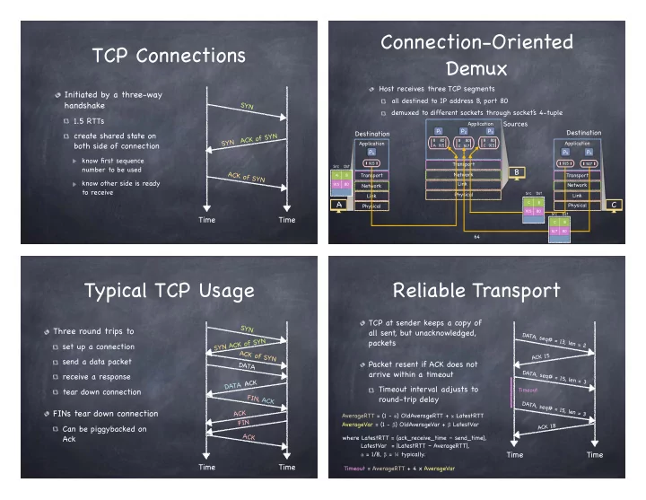
Connection-Oriented TCP Connections Demux Host receives three TCP - - PowerPoint PPT Presentation

connection oriented tcp connections demux
SMART_READER_LITE
LIVE PREVIEW

Connection-Oriented TCP Connections Demux Host receives three TCP - - PowerPoint PPT Presentation

Connection-Oriented TCP Connections Demux Host receives three TCP segments Initiated by a three-way all destined to IP address B, port 80 handshake SYN demuxed to different sockets through socket s 4-tuple 1.5 RTTs Sources Application P 1


slide-1
SLIDE 1

TCP Connections

Initiated by a three-way handshake

1.5 RTTs create shared state on both side of connection

know first sequence number to be used know other side is ready to receive

Time Time

SYN ACK of SYN A C K

  • f

S Y N S Y N

Connection-Oriented Demux

Host receives three TCP segments

all destined to IP address B, port 80 demuxed to different sockets through socket’ s 4-tuple

Application Transport Network Link Physical

80

P1 P2 Application Transport Network Link Physical

915

P4 Application Transport Network Link Physical

915

P5

Sources Destination Destination

B A C

915 80 A B Src Dst

64

B A 915 80 B C 517 80 B C 915

P3

517 80 C B Src Dst 915 80 C B Src Dst 517

P6

Typical TCP Usage

Three round trips to

set up a connection send a data packet receive a response tear down connection

FINs tear down connection

Can be piggybacked on Ack Time Time

SYN ACK of SYN A C K

  • f

S Y N S Y N DATA D A T A A C K FIN, ACK A C K F I N A C K

Reliable Transport

TCP at sender keeps a copy of all sent, but unacknowledged, packets Packet resent if ACK does not arrive within a timeout Timeout interval adjusts to round-trip delay Time Time

DATA, seq# = 13, len = 2 ACK 15 DATA, seq# = 15, len = 3 DATA, seq# = 15, len = 3 ACK 18 Timeout AverageRTT = (1 - ) OldAverageRTT + LatestRTT AverageVar = (1 - ) OldAverageVar + LatestVar where LatestRTT = (ack_receive_time – send_time), LatestVar = |LatestRTT – AverageRTT|, = 1/8, = ¼ typically. Timeout = AverageRTT + 4 x AverageVar

slide-2
SLIDE 2

Pipelining

Sender allows multiple, “in flight”, yet-to-be- acknowledged packets (a “window”)

Increases throughput Needs buffering at sender and receiver

How large should the window be? What if a packet in the middle is missing?

Data packet Ack packet Data packet Ack packet

How Much Data “Fits” in a Pipe?

Suppose

bandwidth is b bytes/sec RTT is r seconds ACK is a small message

then, can send b·r bytes before receiving ack for first byte…

  • f course, b and r can change over time…

TCP Window, Size 4

ack=18 DATA, seq=17 DATA, seq=18 DATA, seq=19 DATA, seq=20 ack=19 ack=20 ack=21 DATA, seq=21 DATA, seq=22 DATA, seq=23 DATA, seq=24

When first item in window is acknowledged, sender can send the 5th item.

TCP Congestion Control

Additive Increase/Multiplicative Decrease (AIMD)

window_size++ every RTT if no packet dropped window_size/2 if packet is dropped

drop detected by acknowledgments

Slowly builds to max bandwidth, and hovers there

Does not achieve maximum bandwidth Shares bandwidth well with other TCP connections TCP friendliness: linear increase, exponential backoff under congestion

slide-3
SLIDE 3

TCP Window Size

Time Bandwidth Max Bandwidth

Linear Increase Exponential Backoff

Assuming losses in the network

  • nly due to bandwidth

Window Size: 1, 2, 3, 4, 5, 6, 7, 8, 9, 10 5, 6, 7, 8, 9, 10 5, 6, 7, 8, 9, 10 …

TCP Slow Start

Linear Increase

Most file transactions end before that happens… It takes long to reach window size that matches b·r

Exponential Increase

TCP builds large window quickly by doubling window size for each ack received until first loss Effectively doubling window size until first loss

TCP Window Size with Exponential Start

Time Bandwidth Max Bandwidth Time Bandwidth Max Bandwidth

TCP Fairness

If k TCP sessions share same bottleneck link

  • f bandwidth R, each should have rate R/k

IS AIMD fair?

Connection 1 Throughput Connection 2 Throughput

Equal Bandwidth Share R R

Start at an arbitrary point

  • 1. Additive Increase

Bandwidth grows equally for both connections: 45o line

slide-4
SLIDE 4

TCP Fairness

If k TCP sessions share same bottleneck link

  • f bandwidth R, each should have rate R/k

IS AIMD fair?

Connection 1 Throughput Connection 2 Throughput

Equal Bandwidth Share R R

Start at an arbitrary point

  • 2. Multiplicative Decrease

Bandwidth halves: half the distance between this point and origin

TCP Fairness

If k TCP sessions share same bottleneck link

  • f bandwidth R, each should have rate R/k

IS AIMD fair?

Connection 1 Throughput Connection 2 Throughput

Equal Bandwidth Share R R

Start at an arbitrary point Bandwidth grows equally for both connections: 45o line

  • 1. Additive Increase

TCP Fairness

If k TCP sessions share same bottleneck link of bandwidth R, each should have rate R/k IS AIMD fair?

Connection 1 Throughput Connection 2 Throughput

Equal Bandwidth Share R R

Start at an arbitrary point Bandwidth halves: half the distance between this point and origin

  • 2. Multiplicative Decrease

Converges around equal bandwidth

TCP Summary

Reliable ordered message delivery

Connection oriented, 3-way handshake

Transmission window for better throughput

Timeouts based on link parameters

Congestion control

Linear increase, exponential backoff

Fast adaptation

Exponential increase in the initial phase

slide-5
SLIDE 5

Link Layer

Application Transport Network Link Physical 79

Network Layer

Application Transport Network Link Physical 80

Internetworking

Connect together multiple local area networks

Nodes with multiple NICs can serve as the glue

In the beginning…

Expensive supercomputers scattered throughout US Researchers not necessarily colocated with them DoD interested in building a resilient global network

ARPAnet: a complex system with simple components

Internet Overview

Every host is assigned, and is identified by, and IP address Messages are called datagrams

packet is more commonly used…

Header in datagram specifies destination address Network routes datagram from source to destination

slide-6
SLIDE 6

IP: Internet’ s Narrow Waist

from: http:/ /if-we.clients.labzero.com/code/posts/what-title-ii-means-for-tcp/

Application Layer Transport Layer Network Layer Data Link Layer Physical Layer

IP Addressing

Every (active) NIC has an IP address

IPv4: 32-bit descriptor, e.g. 128.84.12.43 IPv6: 128-bit descriptor (but only 64 bits “functional”)

Each Internet Service Provider (ISP) owns a set of IP addresses ISPs assign IP addresses to NICs IP address not a unique identifier

Can be reused Same NIC can have different IP addresses over time

Ip Subnetting

N-bit suffix identifies subnet

Either as a number (Ex: 128.84.32.00/24) Or as a “netmask” (Ex.: 255.255.255.0) Within it, has 232-N addresses (hosts)

Big subnets: short prefix, long suffix

Short subnets: long prefix, short suffix

Suffix of “all 0” or “all 1” reserved for broadcast

}

32 bits

IP address

}

24 bits Prefix Suffix

Datagram Forwarding Table

Destination Address Range Link Interface

11001000 00010111 00010000 00000000 through 11001000 00010111 00010111 11111111 11001000 00010111 00011000 00000000 through 11001000 00010111 00011000 11111111

1

11001000 00010111 00011001 00000000 through 11001000 00010111 00011111 11111111

2

  • therwise

3

What if they don’ t divide up so nicely?

slide-7
SLIDE 7

Look for the longest address prefix matching the destination address

Longest prefix matching

Destination Address Range Link Interface

11001000 00010111 00010*** ******** 11001000 00010111 00011000 ********

1

11001000 00010111 00011*** ********

2

  • therwise

3

What is the link interface if the DA is 11001000 00010111 00011000 10101010?

How to Get an IP Address

Hard-coded by system admin in a file

Unix: / etc/rc.config

DHCP: Dynamic Host Configuration Protocol

dynamically get address from DHCP server scales only to a single subnet

DHCP Server 128.84.96.91 128.84.96.90 My physical address is 1a:34:2c:9a:de:cc. What is my IP address? Your IP address is 128.84.96.89 for the next 24 hours

NAT: Network Address Translation

Rest of Internet Local network

10.0.0.1 10.0.0.2 10.0.0.3 10.0.0/24 10.0.0.4 128.84.96.7

all datagrams leaving local network have the same single NAP IP address (128.84.96.7) but different source port numbers datagrams with source or destination in this network have 10.0.0/24 address for source, destination (as usual)

NAT: Motivation

To the rest of the world, local network appears as a single IP address

local IP addresses can be assigned locally, not from ISP address inside local network can change without informing outside world ISP can change without changing addresses of local network devices inside local network not explicitly addressable from outside world (+1 for security)

slide-8
SLIDE 8

How NAT Works

10.0.0.1 10.0.0.2 10.0.0.3 10.0.0.4 128.84.96.7 NAT Translation Table

WAN side address LAN side address 128.84.96.7, 5001 10.0.0.1, 3345

Host 10.0.0.1 sends datagram to 128.119.40.186, 80

1

S: 10.0.0.1, 3345 D: 128.119.40.186, 80

1

NAT router changes source addr from 10.0.0.1, 3345 to 128.84.96.7, 5001 and updates table

2

S: 128.84.96.7, 5001 D: 128.119.40.186, 80

2

Reply arrives: dest address: 128.84.96.7, 5001

3

S: 128.119.40.186, 80 D: 128.84.96.7, 5001

3

NAT router changes dest addr from 128.84.96.7, 5001 to 10.0.0.1, 3345 and updates table

4

S: 128.119.40.186, 80 D: 128.84.96.7, 5001

4

Network-layer Functions

Forwarding (Data plane)

move packets from router’ s input to appropriate router output

Routing (Control plane)

determine route taken by packets from source to destination

Two approaches to structuring control plane:

per-router control logically-centralized control (Software Defined Networking)

Per-Router Control Plane

Local forwarding table Header Output 0100 3 010 2 0111 2 1001 1

Routing Algorithm

Control plane Data plane Routing algorithm components in each and every router interact with each other in control plane to compute forwarding tables

Logically Centralized

Control Plane

A distinct (typically remote) controller interacts with local control agents (CAs) in routers to compute forwarding tables

CA CA CA CA CA

Remote Controller

Control plane Data plane