Composing Transformation Composing Transformation Composing - - PowerPoint PPT Presentation

composing transformation composing transformation
SMART_READER_LITE
LIVE PREVIEW

Composing Transformation Composing Transformation Composing - - PowerPoint PPT Presentation

Composing Transformation Composing Transformation Composing Transformation the process of applying Matrix multiplication is associative several transformation in succession to form one M3 x M2 x M1 = (M3 x M2) x M1 = M3 x (M2 x


slide-1
SLIDE 1

Composing Transformation

Composing Transformation – the process of applying

several transformation in succession to form one

  • verall transformation

If we apply transform a point P using M1 matrix first,

and then transform using M2, and then M3, then we have: (M3 x (M2 x (M1 x P ))) = M3 x M2 x M1 x P

M

(pre-multiply)

Composing Transformation

  • Matrix multiplication is associative

M3 x M2 x M1 = (M3 x M2) x M1 = M3 x (M2 x M1)

  • Transformation products may not be commutative A x B != B

x A

  • Some cases where A x B = B x A

A B translation translation scaling scaling rotation rotation uniform scaling rotation (sx = sy)

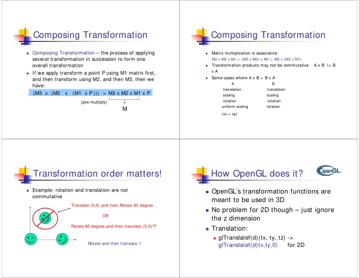
Transformation order matters!

Example: rotation and translation are not

commutative

Translate (5,0) and then Rotate 60 degree OR Rotate 60 degree and then translate (5,0)?? Rotate and then translate !!

How OpenGL does it?

OpenGL’s transformation functions are

meant to be used in 3D

No problem for 2D though – just ignore

the z dimension

Translation:

glTranslatef(d)(tx, ty, tz) ->

glTranslatef(d)tx,ty,0) for 2D

slide-2
SLIDE 2

How OpenGL does it?

Rotation:

glRotatef(d)(angle, vx, vy, vz) ->

glRotatef(d)(angle, 0,0,1) for 2D

x y z

(vx, vy, vz) – rotation axis x y You can imagine z is pointing out

  • f the slide

OpenGL Transformation Composition

A global modeling transformation matrix

(GL_MODELVIEW, called it M here)

glMatrixMode(GL_MODELVIEW)

The user is responsible to reset it if necessary

glLoadIdentity()

  • > M = 1 0 0

0 1 0 0 0 1

OpenGL Transformation Composition

Matrices for performing user-specified

transformations are multiplied to the model view global matrix

For example,

1 0 1

glTranslated(1,1 0); M = M x 0 1 1

0 0 1

All the vertices P defined within glBegin() will first go

through the transformation (modeling transformation) P’ = M x P

Transformation Pipeline

Object Local Coordinates Object World Coordinates Modeling transformation

slide-3
SLIDE 3

Something noteworthy

Very very noteworthy …

  • OpenGL postmultiply each new transformation matrix

M = M x Mnew

  • Example: perform translation, then rotation

0) M = Identity 1) translation T(tx,ty,0) -> M = M x T(tx,ty,0) 2) rotation R(θ) -> M = M x R(θ) 3) Now, transform a point P -> P’ = M x P = T(tx, ty, 0) x R(θ) x P

Wrong!!!

Example Revisit

We want rotation and then translation Generate wrong results if you do:

glRotated(60,0,0,1); glTranslated(5,0,0); glBegin() glTranslated(5,0,0); glRotate(60,0,0,1); glBegin() … You need to specify the transformation in the opposite order!!

How Strange …

OpenGL has its reason … It wants you to think of transformation in a

different way

Instead of thinking of transform the object in

a fixed global coordinate system, you should think of transforming an object as moving (transforming) its local coordinate system

When use OpenGL, we need to think

  • bject transformations as moving

(transforming) its local coordinate frame

All the transformations are performed

relative to the current coordinate frame

  • rigin and axes

OpenGL Transformation

slide-4
SLIDE 4

Translate Coordinate Frame

Translate (3,3)?

Translate Coordinate Frame (2)

Translate (3,3)?

Rotate Coordinate Frame

Rotate 30 degree?

30 degree

Scale Coordinate Frame

Scale (0.5,0.5)?

slide-5
SLIDE 5

Compose Transformations

(7,9) 45 o

Answer:

1. Translate(7,9) 2. Rotate 45 3. Scale (2,2)

Transformations?

Another example

(5,5) 60 o

How do you transform from C1 to C2?

Translate (5,5) and then Rotate (60) OR Rotate (60) and then Translate (5,5) ???

Answer: Translate(5,5) and then Rotate (60)

C1 C2

Another example (cont’d)

60 o

If you Rotate(60) and then Translate(5,5) …

60 o 5 5 C1 C2 You will be translated (5,5) relative to C2!!

Transform Objects

What does coordinate frame transformation

have anything to do with object transformation?

You can view transformation as to tie the

  • bject to a local coordinate frame and

move that coordinate frame

slide-6
SLIDE 6

Example

Old way: Transformation as moving the object relative to the origin of a global world coordinate frame (5,0)

60

  • 1) Rotate ( )

2) Translate (5,0)

60

  • Example (cont’d)

If you think of transformations as moving the local coordinate frame 1) Translate (5,0) 2) Rotate ( )

60

  • (5,0)

60

  • Exact the opposite order compared to the

previous slide!!

So …

If you think of transformations as moving the object relative to the origin of a global world coordinate frame (5,0)

60

  • 1) Rotate ( ) - MR

2) Translate (5,0) - MT P’ = MT x MR x P is the Correct multiplication

60

  • Unfortunately, OpenGL will do MR x MT x P if you call

glRotate() first, and then glTranslate() because of postmultiplication

So … (cont’d)

If you think of transformations as moving the coordinate frame

(5,0) 60

  • 1) Translate (5,0) - MT

2) Rotate ( ) - MR

60

  • So if you think in terms of moving coordinate frames, you will want

to perform Translate first, and then Rotate (I.e., call glTranslate() first and then glRotate()) OpenGL will do MT x MR x P -> The correct multiplication order!!!

slide-7
SLIDE 7

Put it all together

When you use OpenGL …

Think of transformation as moving coordinate

frames

Call OpenGL transformation functions in that

  • rder

OpenGL will actually perform the

transformations in the reverse order

Everything will be just right!!!

Change Coordinate System (1)

What constitutes a coordinate system? Origin O Basis vector i, j Any point P (x,y) in the coordinate system can be represented: P = O + x * i + y * j

i j O

Change Coordinate System (2)

Transform a coordinate system

We can denote the transformation of coordinate systems as C’ = M x C O I’ J’ C’ I J O’ C O’ = M x O I ’ = M x I J’ = M x J (Note that when we transform a vector (a,b), we use (a,b,0) to multiply with the 3x3 matrix M (as opposed to (a,b,1) like we do for points

Change Coordinate System (3)

Assuming P (c, d) in C’, and C’ is obtained by

transforming C using M, i.e., C’ = M x C

O I J C O’ I’ J’ C’ P = (c,d) c d M

Then the coordinates for P in C is P’ = M x P (a,b,1) = M x (c,d,1)

a b

slide-8
SLIDE 8

Successive Coordinate Changes

C1 M1 C2

C1 C2 C3

M1 M2

Given P (a3,b3) in C3 What is P’s coordinates in C1?

M2 (a3,b3) C3 a3 b3

1) Get P’s coordinates in C2 P_c2 = M2 x P 2) Get P_c2’s coordinates in C1 P_c1 = M1 x P_c2 P_c1 = M1 x M2 x P the answer!!

Change Coordinate System (4)

What does it have anything to do with object

transformation?

We can view transformation as moving the

coordinate system (reference frame) and tie the

  • bject with that frame

O’ I J C (c,d) a b a c b = M x d 1 1 What is (a,b)? The coordinates Of the point P (c,d) in C after the coordinate system change i.e, the new coordinates after transforming (c,d) O’ I’ J’ C’ (a,b) c d

Look at transformation again…

C1 M2 (c,d) C3 a3 b3 (c,d) M1 C2 (c,d)

Think transformation of point P (c,d) as a sequence of coordinate frame change P (c,d) is always tied to the (local) coordinate frame P’s final position after the Transformations?

  • > (c,d)’s coordinates in C1

Look at transformation again (2)

C1 M2 (c,d) C3 c d (c,d) M1 C2 (c,d)

Tell OpenGL to transform Using:

M1 (move C1 to C2) M2 (move C2 to C3) P’s final coordinates = P’s coordinates in C1 = M1 x M2 x P This is what we want, and exactly what OpenGL does!! i.e. Apply the last transformation (M2) to the point first

slide-9
SLIDE 9

In other words: If you think of

transformations as changing coordinate frames, the order that you specify the transformations (for the frames) will be exactly opposite to the order that the transformations are actually applied (i.e. matrix- multiplied) to the object

Look at transformation again (3)

Put it all together

Coordinate system transformation

Transform an object from coordinate system C1 with

the origin at (x1,y1) or (x1,y1,z1) in 3D, to coordinate system C2 with the origin (x2,y2) or (x2,y2,z1) in 3D

(x2,y2) (x1,y1) 1. Find the transformation sequence to move C2 to C1 (so C2 will align with C1)

  • Move the origin of C2 to coincide with the
  • rigin of C1
  • Rotate the basis vectors of C2 so that they

coincide wih C1’s.

  • Scale the unit if necessary

2. Apply the above transformation sequence to the

  • bject in the opposite order

c1 c2