CME 310 Solar Power for Africa Overview of Off Grid Photovoltaic - - PowerPoint PPT Presentation

cme 310 solar power for africa overview of off grid
SMART_READER_LITE
LIVE PREVIEW

CME 310 Solar Power for Africa Overview of Off Grid Photovoltaic - - PowerPoint PPT Presentation

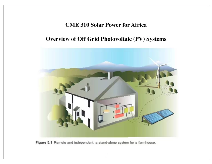
CME 310 Solar Power for Africa Overview of Off Grid Photovoltaic (PV) Systems 1 1) PV Panels 2) Other sources of Power: Wind Turbine, Diesel or Gasoline Generator, Hydropower 3) Charge Controllers 4) Battery Bank 5) AC Inverter/Direct DC


slide-1
SLIDE 1

1

CME 310 Solar Power for Africa Overview of Off Grid Photovoltaic (PV) Systems

slide-2
SLIDE 2

2

1) PV Panels 2) Other sources of Power: Wind Turbine, Diesel or Gasoline Generator, Hydropower 3) Charge Controllers 4) Battery Bank 5) AC Inverter/Direct DC systems 6) Fuse box(es) 7) Appliances/Loads

slide-3
SLIDE 3

3

Process for design of an off-grid PV system 1) Determine the needed AC and DC loads Typically DC is for lighting and any RV type appliances that inhabitants are willing to accept as substitution for AC appliances (you loose ~50% of the power in conversion to AC) The entire system is designed around the anticipated load for an off-grid system and typically it is difficult or impossible to increase this load with the existing system once it is built. So off-grid systems are inflexible in terms of the load. Peak load controls the cost of every component in the system. 2) The total cost (including cost to the environment per kW-hr from the PV system needs to be carefully compared to alternatives Increased insulation and energy conservation Other solar energy sources of heating Biomass and wood heat etc. 3) Once the AC and DC loads are determined the voltage of the PV/Battery system is decided based on the load, distance of transmission from PV to batteries, available battery and PV module voltages and associated costs, step-up or step-down needed for appliance voltage and the associated loss, inverter/charge controller costs. 4) Location for the PV modules must be determined and the solar irradiance must be determined to estimate the power output of the PV modules, the optimal location and the

  • ptimal tilt of the PV modules. The need for a tower or other support structures, distance
  • f transmission from PV modules to batteries and needed cabling must be determined.

5) A ventilated housing for the battery bank must be constructed (produces H2 and O2 and contains sulfuric acid, batteries may require routine maintenance.

slide-4
SLIDE 4

4

Process for design of an off-grid PV system 1) Determine the needed AC and DC loads 2) Compared to alternatives 3) Voltage of the PV/Battery system 4) Location for the PV modules 5) A ventilated housing for the battery bank must be constructed 6) A detailed plan for burying power cables, grounding and other safety issues needs to be

  • developed. PV modules CAN NOT BE TURNED OFF so consideration of means to block

the modules during repair and routine maintenance needs to be considered. 7) A plan for wiring of the facility needs to be developed and the costs assessed including appropriate circuit breakers and grounds.

slide-5
SLIDE 5

5

Process for design of an off-grid PV system 1) Determine the needed AC and DC loads 2) Compared to alternatives 3) Voltage of the PV/Battery system 4) Location for the PV modules 5) A ventilated housing for the battery bank must be constructed 6) A detailed plan for burying power cables, grounding and other safety issues needs to be

  • developed. PV modules CAN NOT BE TURNED OFF so consideration of means to block

the modules during repair and routine maintenance needs to be considered. 7) A plan for wiring of the facility needs to be developed and the costs assessed including appropriate circuit breakers and grounds.

slide-6
SLIDE 6

6

slide-7
SLIDE 7

7

slide-8
SLIDE 8

8

slide-9
SLIDE 9

9

Batteries Batteries are the most important component for an off-grid PV system Deep-Cycle Lead-Acid Batteries are needed (different than car batteries) Car Battery: Large current for short times not substantially discharged PV battery smaller currents for longer times with routine discharge cycles (In developing countries car batteries are sometimes used due to availability) Self-discharge rates of 3%/month Coulombic or charge efficiency 85% percent of charge put in that comes out Voltage efficiency 90% of voltage when discharged Energy efficiency 75% Coulombic * Voltage Flooded or Wet cell: liquid electrolyte must be topped up with DI water, need ventilation for H2, O2 versus Sealed or Valve-regulated cell: gas tight valve allows gas to escape on overpressure H2, O2 make water internally Gel electrolyte sealed battery. Sealed batteries require low maintenance but are more expensive

slide-10
SLIDE 10

10

Batteries Battery capacity: Ampere Hours (Ah), product of current supplied and time 12V battery provides 20 A for 10 hr is a 200 Ah battery (at 20°C at the 10 hour rate) (slower discharge leads to larger capacity, lower temperature leads to lower capacity 1% per degree) For PV we are interested in 100 hour rate A 200 Ah battery at 12V can provide 2.4 kWh total energy storage. The PV array must produce more voltage than the battery in order for the system to work. So we need to know how the voltage of the batter varies during charging and discharging.

slide-11
SLIDE 11

11

Batteries 12V 200 Ah battery shown for constant current discharge 20 A for 10 hours or 2 A for 100 hours 11 V is where damage to battery occurs For extended discharged state sulphation occurs: lead sulphate crystals form on the plates

slide-12
SLIDE 12

12

Batteries Fluctuations in sunlight occur over a daily and over a seasonal schedule These must be planned for in design of the off-grid system

slide-13
SLIDE 13

13

Charge Controllers Control the flow of current from PV array into the battery bank and from battery bank to loads Prevent overcharging of the batteries and over-discharging when demand exceeds supply by disconnecting PV array above 14V for float charging, 14.4 for boost charging and 14.7 for equalization charging in a flooded 12 V battery. Prevent excess discharging by disconnecting the load when voltage falls to 11 V. Protects the batteries.

slide-14
SLIDE 14

14

Charge Controllers

slide-15
SLIDE 15

15

Charge Controllers

slide-16
SLIDE 16

16

Inverters 5 Inverter AC offers flexibility to use “normal” household devices Grid connected inverters must match frequency and phase to match the grid Off-grid is self-commutated

slide-17
SLIDE 17

17

Inverters High Inverter Efficiency means smaller battery bank and PV array

slide-18
SLIDE 18

18

Inverters High Inverter Efficiency means smaller battery bank and PV array Red = low frequency transformer Yellow = high frequency transformer

slide-19
SLIDE 19

19

Hybrid Systems

slide-20
SLIDE 20

20

Hybrid Systems Diesel-PV Hybrid System

slide-21
SLIDE 21

21

Hybrid Systems

slide-22
SLIDE 22

22

System Sizing Sizing problem is the most difficult of system design Estimate the total amount of electricity required on an average day.

slide-23
SLIDE 23

23

System Sizing

slide-24
SLIDE 24

24

System Sizing

slide-25
SLIDE 25

25

System Sizing

slide-26
SLIDE 26

26

System Sizing

slide-27
SLIDE 27

27

System Sizing

slide-28
SLIDE 28

28

System Sizing

slide-29
SLIDE 29

29

Water Pump in Developing World

slide-30
SLIDE 30

30