
SLIDE 1
1
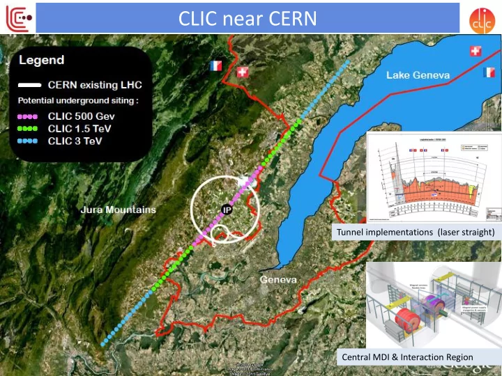
Tunnel implementations (laser straight) Central MDI & Interaction Region
CLIC near CERN Tunnel implementations (laser straight) Central MDI - - PowerPoint PPT Presentation
CLIC near CERN Tunnel implementations (laser straight) Central MDI & Interaction Region 1 Physics at LC from 250 GeV to 3000 GeV Physics case for the Linear Collider: Higgs physics (SM and non-SM) Top SUSY
1
Tunnel implementations (laser straight) Central MDI & Interaction Region
2
Specific challenges for CLIC studies:
for measurements at higher energies
and proton-proton at higher energies (FCC).
References: CLIC CDR and http://arxiv.org/pdf/he p-ex/0112004.pdf, see also talk S.Dawson
140 ms train length - 24 24 sub-pulses 4.2 A - 2.4 GeV – 60 cm between bunches 240 ns 24 pulses – 101 A – 2.5 cm between bunches 240 ns 5.8 ms
4
Key features:
spacing (experimental conditions)
5
Drive beam scheme:
test beam above specifications, deceleration as expected
losses, more deceleration studies underway Main Linac gradient:
10-7, 100 MV/m)
tested Luminosity performance:
no show stopper
better system in pipeline
verification studies in FACET and ATF on-going Implementation:
scenario defined
presented
CLIC timing structure demanding:
physics objects with very high precision
2013-18 Development Phase
Develop a Project Plan for a staged implementation in agreement with LHC findings; further technical developments with industry, performance studies for accelerator parts and systems, as well as for detectors.
2018-19 Decisions
On the basis of LHC data and Project Plans (for CLIC and other potential projects), take decisions about next project(s) at the Energy Frontier.
4-5 year Preparation Phase
Finalise implementation parameters, Drive Beam Facility and other system verifications, site authorisation and preparation for industrial procurement. Prepare detailed Technical Proposals for the detector-systems.
2024-25 Construction Start
Ready for full construction and main tunnel excavation.
Construction Phase
Stage 1 construction of CLIC, in parallel with detector construction. Preparation for implementation
Commissioning
Becoming ready for data- taking as the LHC programme reaches completion.
DRIVE BEAM
CLEX
CLIC Experimental Area
DELAY
COMBINER RING
CTF3 – Layout
10 m
4 A – 1.2 ms 150 MeV 28 A – 140 ns 150 MeV
Two-Beam Test Stand (TBTS) Test Beam Line (TBL)
Critical issues for next phase: Design and Implementation studies:
industrial costing, very limited reliability studies X-band developments:
System-tests:
convincing strategy for further system verification, programmes for use of Xband techology for other applications in its infancy
Technology developments:
assumed, no complete module
29 Countries – over 70 Institutes Accelerator collaboration Detector collaboration Accelerator + Detector collaboration