
SLIDE 1
2018/10/17 1
Chapter 4
Gates and Circuits
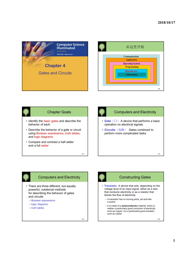
从这里开始
2-2
Communication Application Operating System Programming
Hardware
Information
4–3
Chapter Goals
- Identify the basic gates and describe the
behavior of each
- Describe the behavior of a gate or circuit
using Boolean expressions, truth tables, and logic diagrams
- Compare and contrast a half adder
and a full adder
4–4
Computers and Electricity
- Gate(门) A device that performs a basic
- peration on electrical signals
- Circuits(电路) Gates combined to
perform more complicated tasks
4–5
Computers and Electricity
- There are three different, but equally
powerful, notational methods for describing the behavior of gates and circuits
– Boolean expressions – logic diagrams – truth tables
4–6
Constructing Gates
- Transistor A device that acts, depending on the