challenges in the design of high energy storage flywheels
play

CHALLENGES IN THE DESIGN OF HIGH ENERGY STORAGE FLYWHEELS MADE OF - PDF document

18 TH INTERNATIONAL CONFERENCE ON COMPOSITE MATERIALS CHALLENGES IN THE DESIGN OF HIGH ENERGY STORAGE FLYWHEELS MADE OF COMPOSITE MATERIAL V.Antonelli 1 , P. He 1* , H. Baier 1 1 Institute of Lightweight Structures, Technische Universitt


  1. 18 TH INTERNATIONAL CONFERENCE ON COMPOSITE MATERIALS CHALLENGES IN THE DESIGN OF HIGH ENERGY STORAGE FLYWHEELS MADE OF COMPOSITE MATERIAL V.Antonelli 1 , P. He 1* , H. Baier 1 1 Institute of Lightweight Structures, Technische Universität München, Munich, Germany *Corresponding author (he@llb.mw.tum.de) Keywords : flywheel, energy storage, filament winding, press fitting 1 Introduction connected to the motor, the flywheel can be accelerated to a specific angular velocity, consuming In recent years, flywheel technology has received electrical power by the motor, which then operates much attention for industrial energy storage as generator. applications. Due to advances in power electronics, loss reduction techniques such as magnetic bearings As the kinetic energy is directly proportional to  2 , and vacuum enclosures, and the utilisation of it is common to have very high angular velocities, enhanced high-strength/low-density materials, which correspond to large centrifugal loads and thus economical flywheel energy storage (FES) has lead to high circumferential and radial stresses. become a fact. There are numerous application Composite materials have successfully been opportunities envisioned for those kind of flywheels, established in flywheel rotor design for their including transport systems and uninterruptible beneficial material properties, particularly their high power supplies. specific stiffness and strength [2]. They present many advantages compared to conventional energy storage systems based on battery technology, as fast charge and discharge operations, higher energy density (energy storage per unit weight), longer durability and minor environmental concerns. However, less experience with this technology has led to great research efforts in design optimisation aiming at the enhancement of the efficiency of FES systems [1]. The design of a composite flywheel brings along many challenges. Most of them are related to manufacturing and assembling issues and Fig. 1 Schematic drawing of the basic components of a flywheel energy storage system [2]. considerations on what might occur during operation. The present paper describes the parameters that have to be taken into account when designing a composite 3 High efficiency composite flywheels flywheel. The parameters include material properties, 
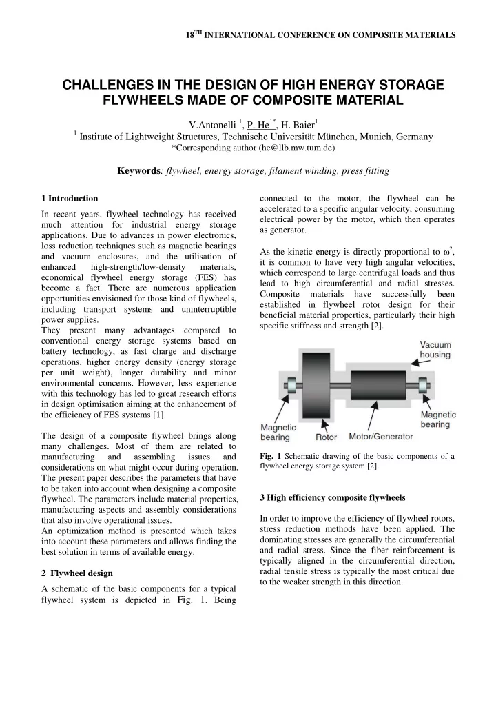
manufacturing aspects and assembly considerations In order to improve the efficiency of flywheel rotors, that also involve operational issues. stress reduction methods have been applied. The An optimization method is presented which takes dominating stresses are generally the circumferential into account these parameters and allows finding the and radial stress. Since the fiber reinforcement is best solution in terms of available energy. typically aligned in the circumferential direction, radial tensile stress is typically the most critical due 2 Flywheel design to the weaker strength in this direction. A schematic of the basic components for a typical flywheel system is depicted in Fig. 1 . Being

  2. Instead of using only one rim material, it is also The interfaces are a crucial design issue and very common to assemble rims of different materials as important considerations have to be made on the shown in Fig. 2 , resulting on a hybrid composite stress level that is allowed during both operation and assembly. flywheel rotor, and/or to apply compressive force between two adjacent rims via press fitting. 3 Theoretical background ring 1 A press-fitted composite flywheel rotor consists of several concentric rings made of different materials. ring 2 The concentric rings are press fitted together with a certain amount of interference. ring 3 Fig. 2 Example of a multi-rim concept. In this case, the radial stresses turn compressive in the region near the material interface due to the lower stiffness of the inner material which would experience greater expansion in the single material case [2]. Fig. 4 Schematic description of two adjacent rings with interference. The method of analytical stress analysis of the flywheel derived from the method proposed by Ha [5] and Krack [6]. The composite flywheel can be assumed to be cylindrically orthotropic and axis symmetric. The Fig. 3 Reduction of radial stresses due to a multirim flywheel. stress distribution in each ring is governed by the radial equilibrium equation, which is written in cylindrical coordinates [6]: Press fitting one ring within another, results in residual compressive stresses in the rings which   2  1       counter the tensile radial stresses that result during rr ( ) r 0 (1)   rr r r rotation. For this purpose, according to literature [3], the material to be chosen should be with increasing where σ rr and σ ϴϴ are the radial and hoop stress, stiffness per density value E/  for increasing radius respectively, ω is the angular velocity and  is the r . density of a ring. In order to verify this statement, an optimization For the 2D plane stress analysis of a cylindrically program has been created which is able to calculate orthotropic ring, the equation the original material the allowable maximum energy for a multi-rim rotor flywheel with interfaces [4].

  3. CHALLENGES IN THE DESIGN OF HIGH ENERGY STORAGE FLYWHEELS MADE OF COMPOSITE MATERIAL laws for an anisotropic material in a cylindrical and can be expanded for a series of rims with cohordinate system can be simplified as: interfaces.         E v E 1   4 Optimisation  1 12 2       (2)   E    v E E     2 2 rr 1 v 12 2 2 rr 12 For a hybrid flywheel rotor composed of N rim E 1 composite rims, the total available energy E total of the flywheel rotor can be calculated as follows: The kinematic laws (strain-displacement relations) are given by:    N  rim     2 4 4 (9) E h r r  total i ( i ) outer ( i ) inner u r u r 4      i 1 ,  (3)  rr r r In Eq. (9) h is the height, ω is the angular velocity of the rotor, and ρ i is the density of the i-th rim. Substituting equations (2) and (3) into equation (1) results in the following equation for u : Strength ratio R is used for failure analysis, where a value of R greater than 1 indicates material failure.  In the present program, the maximum stress failure 2 2 d u 1 du Q u     r r 11 r r (4) criterion is used, the Strength ratio R for this case 2 2 dr r dr Q r Q 33 33 can then be computed by:  After solving the differential equation (4), the    h 0 R , for following results will be obtained [6]: 1 t h T X        2     h (5) 3 k k 0 R , for u r C r C r h 1 c r 0 1 2 C X (10)                (6) 2 2 k 1 k 1  r C r C r r 0 R , for rr 1 1 2 2 3 2 t r T Y               (7) 2 2 k 1 k 1 w r C r C r    r 0 4 1 5 2 6 R , for 2 c r C Y where C1 and C2 are unknown constants and will be Herein X T , Y T , X C , Y C , denote the material strengths determined from boundary conditions and : in the longitudinal and transverse direction for tensile and compressive values respectively. Q   11 Q When inner and outer flywheel radii are constant 33 parameters, the optimization problem for a hybrid 1     flywheel rotor of N rim press fitted rims is thus  0 2 9 k Q 33 formulated as follows: (8)   0   Q     Q    3 Q , kQ 1 13 33 2 13 33     Find x T , T ,... T , , ,... , n  1 2 1 2 1 Nrim Nrim   0   Q    Q    kQ 3 Q , Maximize f ( x ) E ( x ) 3 13 33 4 11 13 total Subjected to   Q    Q  kQ kQ ,    ; 5 11 13 6 11 13 g ( x ) R ( x ) 1 0 (11)   10 mm T 450 mm Nrim This set of equation allows the calculations of the      13000 rpm n 17000 rpm 0 t stresses and radial displacements of one single rim 1 st    i=2,…N rim -1 and 0 t i comp

Download Presentation
Download Policy: The content available on the website is offered to you 'AS IS' for your personal information and use only. It cannot be commercialized, licensed, or distributed on other websites without prior consent from the author. To download a presentation, simply click this link. If you encounter any difficulties during the download process, it's possible that the publisher has removed the file from their server.

Recommend


More recommend