cavity ring down las er abs orption spectros copy
play

Cavity Ring-Down Las er Abs orption Spectros copy Humberto - PDF document

Cavity Ring-Down Las er Abs orption Spectros copy Humberto Cabrera 1. Introduccin The method is based on measurement of the time rate of decay of a pulse of light trapped in a high reflectance optical cavity; we call it cavity ringdown laser


  1. Cavity Ring-Down Las er Abs orption Spectros copy Humberto Cabrera 1. Introducción The method is based on measurement of the time rate of decay of a pulse of light trapped in a high reflectance optical cavity; we call it cavity ringdown laser absorption spectroscopy (CRLAS). In practice, pulsed laser light is injected into an optical cavity that is formed by a pair of highly reflective ( R > 99.9%) mirrors. The small amount of light that is now trapped inside the cavity reflects back and forth between the two mirrors, with a small fraction (1 - R ) transmitting through each mirror with each pass. The resultant transmission of the circulating light is monitored at the output mirror as a function of time and allows the 
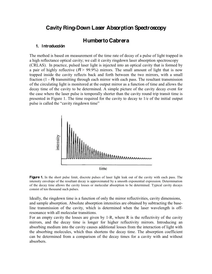
decay time of the cavity to be determined. A simple picture of the cavity decay event for the case where the laser pulse is temporally shorter than the cavity round trip transit time is presented in Figure 1. The time required for the cavity to decay to 1/e of the initial output ���������������������� avity ringdown ����� Figure 1. In the short pulse limit, discrete pulses of laser light leak out of the cavity with each pass. The intensity envelope of the resultant decay is approximated by a smooth exponential expression. Determination of the decay time allows the cavity losses or molecular absorption to be determined. Typical cavity decays consist of ten thousand such pulses. Ideally, the ringdown time is a function of only the mirror reflectivities, cavity dimensions, and sample absorption. Absolute absorption intensities are obtained by subtracting the base- line transmission of the cavity, which is determined when the laser wavelength is off- resonance with all molecular transitions. For an empty cavity the losses are given by 1-R, where R is the reflectivity of the cavity mirrors, and the decay time is longer for higher reflectivity mirrors. Introducing an absorbing medium into the cavity causes additional losses from the interaction of light with the absorbing molecules, which thus shortens the decay time. The absorption coefficient can be determined from a comparison of the decay times for a cavity with and without absorbers.

  2. The high sensitivity stems mainly from the intrinsic insensitivity of CRLAS to laser power fluctuations and the extremely long effective interaction pathlengths (many kilometers) that can be achieved using the optical cavity. Although the CRLAS technique was initially developed for pulsed laser sources it is also possible to do it with continuous-wave (cw) lasers by sweeping the frequency of the laser quickly across the cavity modes. 2. Theory 2.1. Cavity properties Figure 2. Schematic illustration of an optical cavity with length L. The mirrors have reectivity R, transmission T and losses A. In order to sustain a stable Gaussian mode inside the cavity the curvature of the cavity mirrors has to match the curvature of the Gaussian beam. Therefore at least one of the mirrors has to be curved A Fabry-Perot cavity consists basically of two mirrors with high reflectivity and non-zero transmission, as shown in Figure 2. Only the light that is resonant with the cavity, i.e. satisfies the standing wave condition, can be coupled into the cavity and transmitted through it. The transmission spectrum of the cavity, shown schematically in Figure 2, consists therefore of a series of modes with frequencies where q is the cavity mode number, c is the speed of light, and L is the cavity length. The distance between two consecutive cavity modes is the so-called cavity free-spectral range (FSR), which is visualized in Figure 3 and determined solely by the length of the cavity. The width of the cavity modes, � c , is given by the ratio of the spacing of the cavity modes and the cavity Finesse, F, which in turn is determined by the reflectivity, R, of the cavity mirrors

  3. Figure 3. Schematic illustration of an optical cavity with length L. The mirrors have reectivity R, transmission T and losses A. In order to sustain a stable Gaussian mode inside the cavity the curvature of the cavity mirrors has to match the curvature of the Gaussian beam. Therefore at least one of the mirrors has to be curved 2.2. Cavity Ring-Down S pectroscopy First, consider a laser pulse with power P 0 that is coupled into the cavity, which comprises two high reflectivity mirrors with equal reflectivities R. The pulse travels back and forth in the cavity multiple times, and a fraction of it leaks out through the cavity mirrors on each reflection. The transmission of a cavity mirror, T, is given by where A includes the losses from scattering, absorption and diffraction in the cavity mirror coatings. When the cavity is filled with an analyte with absorption coeffcient ���� , the transmitted power after n round-trips in the cavity is where P 1 ( � ) is the transmitted power after the first round-trip, given by Assuming high reflectivities of the mirrors, i.e. �� 1, implies that ln �� R- �� - (T + A), which leads to the following expression for the transmitted power

  4. The time for one round-trip of a pulse in the cavity is t 1 = 2L/c, which implies that the pulse leaking out of the cavity after n reflections will be detected at the time t n = 2nL/c. A detector with a time constant that is larger than t 1 will average over subsequent pulses and record a ring-down event, i.e. an exponential decay of the transmitted power according to where � 1 ( � ) is the decay time in the presence of absorber, given by The decay time in the absence of absorber [ ���� = 0] reduces to This implies that the absorption coeffcient, ������������������������������������� erence of the reciprocal decay times multiplied by c according to In conclusion, it is possible to determine the absorption coeffcient, ���� , by measuring the decay times of the transmitted power of the light with and without absorber, respectively. Alternatively, � 2 can be measured at a frequency far detuned from the molecular transition. When a cw laser is used instead of a pulsed laser, a cavity ring-down signal can be observed if the laser frequency is scanned around the cavity resonance at a high enough rate. In general, the scanning rate should be so high that the laser interacts with the cavity mode over a time much shorter than the ring-down (decay) time. In this way, not all laser power is coupled into the cavity, but the laser frequency is moved away from resonance quickly enough so that only light leaking out of the cavity is detected in cavity transmission. Figure 4 illustrates the general behavior of the CRLAS signals as the laser frequency is scanned across cavity modes. By fitting an exponential function to the decay of each cavity mode with and without absorbers it is possible to determine the ring-down times � 1 ���� � 2 , which can be related to the molecular absorption at the cavity mode frequency through equation (11).

  5. Figure 4. Typical CRLAS signals. 1. Experimental s etup Figure 5. Schematic illustration of the experimental setup. The experimental setup is shown schematically in Figure 5. The source of light is a semiconductor laser. The laser wavelength is controlled with a combined temperature and current driver. The driver has an external voltage input that allows modulating the laser wavelength. A function generator is provided for that purpose. The cavity is made of two mirrors with highly reflective dielectric coatings designed at the laser emission wavelength. The input mirror is flat whereas the output mirror is concave with a 1m radius of curvature. The mirrors are glued to a 60 cm long stainless steel tube that provides mechanical stability and is open to air via two tubes. The fiber-coupled output of the laser is connected to an output collimator, which provides a Gaussian beam profile. An optical isolator is used to prevent optical feedback into the laser, i.e. it prevents the light reflected from the cavity to go back into the laser, which would disturb its single mode operation. The Gaussian beam is mode-matched to the cavity by a mode-matching lens (focal length of 1 m) placed at a correct position prior to cavity. The light that is transmitted through the cavity is focused on

  6. an InGaAs detector with a bandwidth of 5MHz and a gain of 175 kV/W. The detector signal can be observed on an oscilloscope or alternatively recorded with a fast acquisition card (10 MHz) and stored on a computer for analysis.

Download Presentation
Download Policy: The content available on the website is offered to you 'AS IS' for your personal information and use only. It cannot be commercialized, licensed, or distributed on other websites without prior consent from the author. To download a presentation, simply click this link. If you encounter any difficulties during the download process, it's possible that the publisher has removed the file from their server.

Recommend


More recommend