castellated beams new developments
play

Castellated BeamsNew Developments J. P. BOYER This paper was - PDF document

Castellated BeamsNew Developments J. P. BOYER This paper was presented at the AISC National Engineering Conference, Omaha, Nebr., in May, 1964. "CASTELLATED BEAM" is a name commonly used for a Europe because of the limited number of


  1. Castellated Beams—New Developments J. P. BOYER This paper was presented at the AISC National Engineering Conference, Omaha, Nebr., in May, 1964. "CASTELLATED BEAM" is a name commonly used for a Europe because of the limited number of sections avail- type of expanded beam. It is made by expanding a able from European mills and because of the high ratio standard rolled shape in a manner which creates a of material cost to labor cost. regular pattern of holes in the web. The name is derived The investigation was primarily directed toward the from this pattern of web holes, because castellated means Litzka process and equipment which was developed by "built like a castle, having battlements, or regular holes Litzka Stahlbau of Bavaria, Germany. Study and evalua- in the walls, like a castle". tion of this process led to the conclusion that it is particu- 
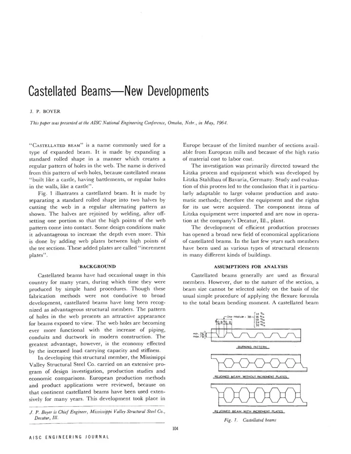
Fig. 1 illustrates a castellated beam. It is made by larly adaptable to large volume production and auto- separating a standard rolled shape into two halves by matic methods; therefore the equipment and the rights cutting the web in a regular alternating pattern as for its use were acquired. The component items of shown. The halves are rejoined by welding, after off- Litzka equipment were imported and are now in opera- setting one portion so that the high points of the web tion at the company's Decatur, 111., plant. pattern come into contact. Some design conditions make The development of efficient production processes it advantageous to increase the depth even more. This has opened a broad new field of economical applications is done by adding web plates between high points of of castellated beams. In the last few years such members the tee sections. These added plates are called "increment have been used as various types of structural elements plates". in many different kinds of buildings. BACKGROUND ASSUMPTIONS FOR ANALYSIS Castellated beams have had occasional usage in this Castellated beams generally are used as flexural country for many years, during which time they were members. However, due to the nature of the section, a produced by simple hand procedures. Though these beam size cannot be selected solely on the basis of the usual simple procedure of applying the flexure formula fabrication methods were not conducive to broad to the total beam bending moment. A castellated beam development, castellated beams have long been recog- nized as advantageous structural members. The pattern of holes in the web presents an attractive appearance for beams exposed to view. The web holes are becoming ever more functional with the increase of piping, conduits and ductwork in modern construction. The greatest advantage, however, is the economy effected BURNING PATTERN by the increased load carrying capacity and stiffness. In developing this structural member, the Mississippi Valley Structural Steel Co. carried on an extensive pro- gram of design investigation, production studies and REJOINED BEAM WITHOUT INCREMENT PLATES economic comparisons. European production methods and product applications were reviewed, because on that continent castellated beams have been used exten- sively for many years. This development took place in J. P. Boyer is Chief Engineer, Mississippi Valley Structural Steel Co.. REJOINED BEAM WITH INCREMENT PLATES Decatur, III. Fig. 7. Castellated beams 104 A I S C E N G I N E E R I N G J O U R N A L

  2. DEVELOPMENT OF BEAM LOAD TABLES It is conceivable that a formula could be established ,B/2, to solve directly for the critical stress of a castellated beam ty h *t 4 H M \ 1,\ 1/ section; however, such a formula would be exceedingly V f b fb M 2 \ complex. The most practical method for designing a At Sect."H" At Sect. " 2 - 2 " ) ) castellated beam is to start with a specific beam section TOTAL 1/ and compute its capacity. That simple statement, how- |V/2|| ever, covers quite a sizeable amount of calculating, since Due To Moment Due To Shear it is necessary to compute many different stress condi- • M _ _ V _ X J . X _ L tions for each beam. Because of this, it was decided by V 2 2 S t Mississippi Valley to devise a series of efficient castellated %-P. beam sections and to calculate and publish their load b B"s;l—5T1 b V~ 2 X 2 " S n \ Dg_ S b capacities for various spans. This has resulted in the 2 publication Design Data for Castellated Beams. 1 At Sect. "1-1" f5 = b g + b y Formula "A" MAXIMUM FIBER STRESS At Sect. "2-2" f t = t B + t v Formula "B" In making design calculations for the castellated beam load tables, the capacities of about 500 different beams were computed for some 20 span lengths. Since this Fig. 2. Fiber stresses involved determining the fiber stress at many points performs like, and may be analyzed as, a Vierendeel along each beam, about 500,000 stress calculations were truss. In such a member the longitudinal fiber stresses, required and a computer program was obviously a real which govern the beam section used, are influenced both benefit. by beam bending moment and vertical shear. To calculate the beam capacities, a simple span The basic design of a castellated beam consists of beam was considered carrying a unit uniform load. analyzing the effect of the forces and calculating the The computer program determined stresses at each of 100 stresses illustrated in Fig. 2. Maximum longitudinal fiber points along the length of the beam and selected the max- stresses occur in the tee section. These stresses may be imum stress and its location. From this maximum stress for readily computed on the basis of the following assump- unit load, the beam capacity for any particular allowable tions which are well verified: stress was readily calculated. In addition to computing the longitudinal fiber stresses, shear stresses and de- 1. Vertical shear divides equally between the upper flections were also determined. These analyses were and lower tees. made for each beam section on each span considered. 2. For bending in the tees due to shear, there are points The load tables give precise data for the selection of of contraflexure at the vertical centerline through castellated beams over a wide range of uniform load each opening. conditions on simple spans. The load tables may also 3. Fiber stresses distribute as illustrated and can be be used to select castellated beams for certain special computed by the formulas shown. concentrated load conditions. As illustrated in the stress distribution diagrams in Fig. 2, maximum longitudinal fiber stresses can occur DESIGN CRITERIA AND PROCEDURES at the inner edge of the tee web, f b , or at the back of the There are conditions, however, which will require tee, f t . Maximum f b would occur at Section 1-1 and be the designer to compute the stresses and capacity of a computed by Formula A. Maximum f t would occur at castellated beam. This may be required for irregular Section 2-2 and be computed by Formula B. A castel- concentrated loads, for cantilever beams, or when there lated beam section is most efficiently used when f t is are special web holes. Under such special conditions the the governing stress. However this is not always possible, designer should select a trial castellated beam section particularly on short spans. by judgment and use of the load tables, and then com- There is an element which adds considerable work pute its stresses using Formulas A and B. to the design of castellated beams. That is, the location The maximum longitudinal fiber stress generally of the maximum fiber stress is unknown; it can occur governs the selection of a beam section, but there are at any point along the length of the beam. Fiber stress other stress conditions which must be examined and f b will be at its optimum in areas of higher shear; fiber controlled. These are lateral buckling, local buckling, stress f t will be at its optimum in areas of high moment. web buckling and web bending and shear stresses. On simple span beams carrying uniform load, the loca- tion of maximum fiber stress can be at any point between the end of the beam (high shear) and mid-span (high 1. Design Data for Castellated Beams, Mississippi Valley moment). Structural Steel Co., 777 West Washington St., Chicago 2, III. 105 J U L Y / 1 9 6 4

Download Presentation
Download Policy: The content available on the website is offered to you 'AS IS' for your personal information and use only. It cannot be commercialized, licensed, or distributed on other websites without prior consent from the author. To download a presentation, simply click this link. If you encounter any difficulties during the download process, it's possible that the publisher has removed the file from their server.

Recommend


More recommend