carbon fiber composites reinforced with carbon
play

CARBON FIBER COMPOSITES REINFORCED WITH CARBON NANOMATERIALS H. Kim - PDF document

18 TH INTERNATIONAL CONFERENCE ON COMPOSITE MATERIALS CARBON FIBER COMPOSITES REINFORCED WITH CARBON NANOMATERIALS H. Kim 1* , H. T. Hahn 2 , E. Bekyarova 3 , E. Oh 4 , G. Lee 4 1 Korea Institute of Science and Technology, Jeonbuk, Korea 2


  1. 18 TH INTERNATIONAL CONFERENCE ON COMPOSITE MATERIALS CARBON FIBER COMPOSITES REINFORCED WITH CARBON NANOMATERIALS H. Kim 1* , H. T. Hahn 2 , E. Bekyarova 3 , E. Oh 4 , G. Lee 4 1 Korea Institute of Science and Technology, Jeonbuk, Korea 2 Mechanical and Aerospace Engineering Department, UCLA, Los Angeles, USA 3 Carbon Solutions, Inc., Riverside, USA 4 Dept. of Chemical Engineeringartment, POSTECH, Pohang, Korea * Corresponding author(hskim@kist.re.kr) Keywords : Nanocomposites, Carbon fiber composites, carbon nanotubes, graphite 1 Introduction 
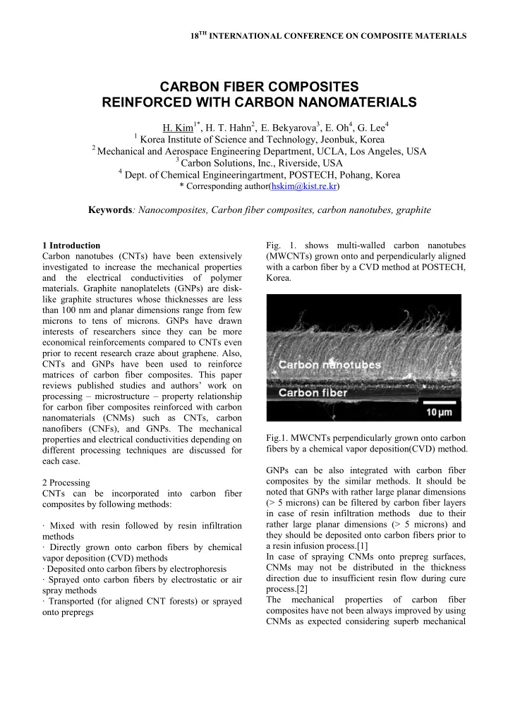
Fig. 1. shows multi-walled carbon nanotubes Carbon nanotubes (CNTs) have been extensively (MWCNTs) grown onto and perpendicularly aligned investigated to increase the mechanical properties with a carbon fiber by a CVD method at POSTECH, and the electrical conductivities of polymer Korea. materials. Graphite nanoplatelets (GNPs) are disk- like graphite structures whose thicknesses are less than 100 nm and planar dimensions range from few microns to tens of microns. GNPs have drawn interests of researchers since they can be more economical reinforcements compared to CNTs even prior to recent research craze about graphene. Also, CNTs and GNPs have been used to reinforce matrices of carbon fiber composites. This paper reviews published studies and authors’ work on processing – microstructure – property relationship for carbon fiber composites reinforced with carbon nanomaterials (CNMs) such as CNTs, carbon nanofibers (CNFs), and GNPs. The mechanical Fig.1. MWCNTs perpendicularly grown onto carbon properties and electrical conductivities depending on fibers by a chemical vapor deposition(CVD) method. different processing techniques are discussed for each case. GNPs can be also integrated with carbon fiber composites by the similar methods. It should be 2 Processing noted that GNPs with rather large planar dimensions CNTs can be incorporated into carbon fiber (> 5 microns) can be filtered by carbon fiber layers composites by following methods: in case of resin infiltration methods due to their rather large planar dimensions (> 5 microns) and ∙ Mixed with resin followed by resin infiltration they should be deposited onto carbon fibers prior to methods a resin infusion process.[1] ∙ Directly grown onto carbon fibers by chemical In case of spraying CNMs onto prepreg surfaces, vapor deposition (CVD) methods CNMs may not be distributed in the thickness ∙ Deposited onto carbon fibers by electrophoresis direction due to insufficient resin flow during cure ∙ Sprayed onto carbon fibers by electrostatic or air process.[2] spray methods The mechanical properties of carbon fiber ∙ Transported (for aligned CNT forests) or sprayed composites have not been always improved by using onto prepregs CNMs as expected considering superb mechanical

  2. properties of individual CNMs.[3] The main reasons and in-plane shear properties can be enhanced by for this less-than-expected mechanical enhancement using CNMs. by using CNMs are as follows: For an example, the mode I fracture toughness of carbon fiber composites was 2.5 times increased by ∙ Achieving good processing quality of carbon fiber inserting vertically aligned multi-walled carbon composites by overcoming problems caus ed by nanotube (MWCNT) forests between carbon fiber adding CNMs. prepreg layers.[5] However, due to the long and stiff ∙ Achieving good dispersion and interfacial adhesion MWCNT layers, the thickness resin-rich region of between CNMs and polymers. the CNT samples was much larger than that of the control samples. This is a reason why processing – A challenge is that the above two problems are microstructure – property relationship is critical to closely related. For instance, the better a dispersion verify the real reinforcement mechanism of carbon of CNMs in a resin system is, the higher the nanotubes in the fiber composites. In another study, viscosity of the solution gets even at a very low a very large increase in the mode-I fracture concentration of the CNMs. This increased viscosity toughness by growing CNTs perpendicularly onto can cause voids inside of the composite after a resin SiC fibers was shown. However, only the initiating infusion process such as a vacuum assisted resin part of the crack propagation was used for the transfer molding (VARTM) method.[4] On the other fracture toughness calculation.[6] hand, reasonably low viscosity due to poor In an authors’ work, MWCNTs were grown onto dispersion of CNMs in resin can lead to good quality carbon fibers as shown in Fig. 1., and the composites of composite samples in terms of voids inside the were processed using a VARTM method. From the composites but the mechanical properties of the results of this study, as long as the adhesion between composites should be poor due to CNM CNTs and carbon fibers is not good, the presence of agglomerates in the composites. CNTs did not increase the mode-I fracture toughness Cumbersome dispersion process of CNMs can be of the carbon fiber composites even though CNTs avoided by direct deposition of CNMs onto carbon were aligned perpendicularly to the carbon fibers fibers prior to resin infusion. In this way, the high (crack propagation direction). Despite of several viscosity problem of the resin for resin infusion studies that showed increased interfacial shear processes can be avoided as well. In case of CNTs strength (IFSS) for CNT-grafted carbon fibers by directly grown onto carbon fibers, adhesion between pull-out test of single fiber/epoxy samples, we have CNTs and carbon fibers is also important for the not seen any reinforcement effect by using aligned mechanical properties such as the mode-I fracture CNTs on carbon fibers at least for the mode-I toughness; otherwise, the presence of CNTs reduces fracture toughness.[7][8] Only after the adhesion the contact area between the fibers and the matrix was enhanced, the mode-I fracture toughness and decreases the mechanical properties controlled showed consistent improvement, Fig. 3. by the interface between the fibers and the matrix. 3 Properties 3.1 Mechanical properties As expected, it is not effective to improve fiber- dominant properties of carbon fiber composites such as the tensile properties by using CNMs since the mechanical properties of carbon fibers are usually two orders of magnitude higher than those of polymer matrices even after reinforced with CNMs.[3] However, the matrix-dominant properties such as the mode-I fracture toughness (resistance to Fig. 3. Fracture toughness results of the composites delamination), the interlaminar shear strength (ILSS), with CNTs grown onto the carbon fibers.

  3. Fig. 4. shows CNTs with good adhesion to carbon fibers are still attached to the carbon fibers even after the mode-I fracture toughness test. Fig. 4. Interlaminar shear strengths (ILSS) of the carbon fiber composites with or without SWCNTs Fig. 4. Strong adhesion between MWCNTs and carbon fibers (a fracture toughness tested sample). Despite the fact that single-walled carbon nanotubes (SWCNTs) have higher mechanical properties and larger aspect ratios than MWCNTs, the composites with SWCNTs have always encountered a big challenge, achieving good dispersion of SWCNTs in the composites. Hence, the SWCNT/polymer composites have not seen much enhancement in the mechanical properties as expected. Carbon fiber composites with SWCNTs are not exceptions. From authors’ results, for ILSS, SWCNT-reinforced carbon fiber samples did not always show improvement over the control samples since increased viscosity of SWCNT/resin mixture and SWCNT agglomerates often caused voids inside of Fig. 5. (a) No voids in a sample without SWCNTs the composites particularly for resin infusion ( x 100) (b) Voids in a sample with 0.2 wt% methods. SWCNTs ( x 100) (c) x 500 micrograph of a sample Fig. 4 shows ILSS results of carbon fiber composites with 0.2 wt% SWCNTs with or without SWCNTs. Increased viscosity of the resin due to dispersion of SWCNT in the epoxy resin For both CNTs and GNPs, functionalization is might have caused voids during resin infusion critical for good bonding between CNMs and process, Fig. 5.[4] And, ILSS is known to be polymer matrices. A study shows that nitric acid sensitive to void contents of fiber composites.[9] treated GNPs are observed to increase the in-plane shear strength of the carbon fiber composites while as untreated GNPs deteriorated the property .[1] 3

Download Presentation
Download Policy: The content available on the website is offered to you 'AS IS' for your personal information and use only. It cannot be commercialized, licensed, or distributed on other websites without prior consent from the author. To download a presentation, simply click this link. If you encounter any difficulties during the download process, it's possible that the publisher has removed the file from their server.

Recommend


More recommend