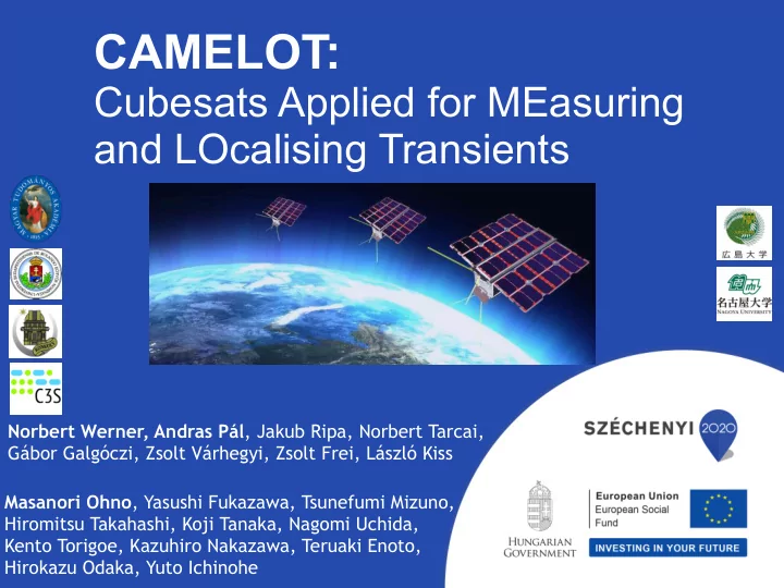
camelot
play

CAMELOT: Cubesats Applied for MEasuring and LOcalising Transients - PowerPoint PPT Presentation

CAMELOT: Cubesats Applied for MEasuring and LOcalising Transients Norbert Werner, Andras Pl , Jakub Ripa, Norbert Tarcai, Gbor Galgczi, Zsolt Vrhegyi, Zsolt Frei, Lszl Kiss Masanori Ohno , Yasushi Fukazawa, Tsunefumi Mizuno,


  1. CAMELOT: Cubesats Applied for MEasuring and LOcalising Transients Norbert Werner, Andras Pál , Jakub Ripa, Norbert Tarcai, Gábor Galgóczi, Zsolt Várhegyi, Zsolt Frei, László Kiss Masanori Ohno , Yasushi Fukazawa, Tsunefumi Mizuno, Hiromitsu Takahashi, Koji Tanaka, Nagomi Uchida, Kento Torigoe, Kazuhiro Nakazawa, Teruaki Enoto, Hirokazu Odaka, Yuto Ichinohe

  2. THE DISCOVERY OF GAMMA RAY BURSTS • discovered in 1967 by the VELA satellites monitoring the nuclear test ban treaty • nuclear explosion in space produces X- rays, gamma rays, and neutrons (no visible radiation or sound) • orbits at altitude of 100,000 km (to be outside radiation belts and to detect � 2 detonations behind the Moon!) • “ 16 gamma-ray bursts of cosmic origin ” published in 1973 (Klebasadel et al. 1973, ApJ, 182, L85)

  3. 17. 08. 2017 THE BEGINNING OF MULTI-MESSENGER ASTROPHYSICS � 3

  4. 17. 08. 2017 THE BEGINNING OF MULTI-MESSENGER ASTROPHYSICS � 3

  5. 17. 08. 2017 THE BEGINNING OF MULTI-MESSENGER ASTROPHYSICS • 5 gravitational wave detections from BH-BH merger • EM counterpart from NS-NS merger event GW170817/ GRB170817A • Large campaign of follow-up observations identified a kilonova • The gamma-ray counterpart is unusual • Regular detections/follow-up observations are needed to make progress � 4

  6. LOCALISATION CRITICAL FOR PROGRESS • Localisation error of GW telescopes is several tens of degree 2 • FoV of optical telescope providing follow up observations is of the order of ~1 deg • Quick localisation of prompt gamma ray emission with a precision of tens of arcmin critical to enable efficient follow up observations R= 3’ � 5 ~15’

  7. AN EMPTY REGION IN PARAMETER SPACE Field of view (str) INTEGRAL-SPI-ACS INTEGRAL-SPI-ACS (w/ IPN) 4 π ー CALET-CGBM Fermi-GBM 2 π ー AGILE Fermi-LAT CALET MAXI Swift-BAT Swift-XRT | | | | Localization accuracy degree No localization arcmin arcsec

  8. AN EMPTY REGION IN PARAMETER SPACE Field of view (str) INTEGRAL-SPI-ACS INTEGRAL-SPI-ACS (w/ IPN) 4 π ー CALET-CGBM All-sky coverage Fermi-GBM ➔ Poor loc. acc. 2 π ー AGILE Fermi-LAT X-ray mirror, coded mask CALET MAXI ➔ High loc. acc. But narrow FoV Swift-BAT Swift-XRT | | | | Localization accuracy degree No localization arcmin arcsec

  9. AN EMPTY REGION IN PARAMETER SPACE Field of view (str) INTEGRAL-SPI-ACS INTEGRAL-SPI-ACS No instruments with (w/ IPN) 4 π ー Larger FoV (>2 π str) + CALET-CGBM Good Loc. Acc. (arcmin) All-sky coverage Fermi-GBM ➔ Poor loc. acc. ➔ Discovery space 2 π ー AGILE Fermi-LAT X-ray mirror, coded mask CALET MAXI ➔ High loc. acc. But narrow FoV Swift-BAT Swift-XRT | | | | Localization accuracy degree No localization arcmin arcsec

  10. CAMELOT: CUBESAT ARRAY FOR MEASURING AND LOCALIZING TRANSIENTS Each satellite will use a standard 3U cubesat platform developed by C3S LLC for the ESA A constellation of at least 9 satellites can provide: - all sky coverage with a large e ff ective area sponsored RadCube mission. The cubsesats will - Better than 0.1 millisecond timing accuracy be equipped with a GPS receiver for precise - ~10 arcmin localisation accuracy using time synchronisation and inter-satellite (Iridium NEXT) communication equipment for rapid data triangulation download

  11. THE NEW ERA OF NANOSATELLITES (CUBESATS) skCube Cubesats deployed from the Space Station Standard cubesat sizes

  12. THE NEW ERA OF NANOSATELLITES (CUBESATS) Most cubesats built by private Three epochs of cubesat development: companies and universities, not space 1) Small projects by students and agencies enthusiasts 2) Demonstration of new technology for space applications 3) Breakthrough science and full scale commercial use

  13. THE SATELLITE PLATFORM 3U cubesat developed The platform can be reused with by C3S LLC for the ESA sponsored small modifications for CAMELOT RadCube mission

  14. TWO POSSIBLE DETECTOR CONFIGURATIONS

  15. THE DETECTOR DESIGN The read out of the CsI detectors with MPPC is To maximise the e ff ective area, the detectors based currently being evaluated in the lab as part of our on CsI scintillators and Multi-Pixel Photon Counters feasibility study. The system provides a large light (MPPC) will occupy two lateral extensions (8.3cm x yield, compact readout area and relatively low 15 cm x 0.9cm x 4) operational voltage. The large and thin detectors with small readout area are challenging

  16. Spectral feasibility Preliminary! Effective Area (cm 2 ) Preliminary! 300 100 10 Torigoe+ 2018 Energy (keV) GRB incident zenith angle (deg) Single channel readout Coincidence sum Coincidence sum (scaled) 241 Am 59.5 keV GRB incident horizontal angle (deg) Energy threshold of ~10 keV is achieved Effective area for any incident angle is for both single/multi channel readout estimated by the Monte-Carlo simulation, Energy range: 10-1000 keV (TBD) 200~300 cm 2 (@100 keV) Sensitivity of one satellite is comparable to Fermi-GBM

  17. BLOCK DIAGRAM OF THE CAMELOT PAYLOAD 1 2 3 4 5 6 7 8 9 10 11 12 I I H H GPS Timestamping G G MPPC ADS5295 TCXO GPS Storage MPPC F F MPPC MPPC FPGA/MCU: Low speed E E 8 − channel − timestamping MPPC bus interface FPGA: − interfacing 100MSPS − housekeeping − signal processing ADC − reduction of dataflow MPPC − triggering − correlation analysis D D − noise statistics . MPPC M − LVDS (High speed bus interface) MPPC Core logic C C Power supply (3.3V/5V => 50 − 60V, 1.2V, 1.8V) B B GRBCube − Payload block schematics A A TITLE FILE: REVISION: PAGE OF DRAWN BY: 1 2 3 4 5 6 7 8 9 10 11 12 Pál et al. 2018

  18. CAMELOT GPS TIME- STAMPING TEST BOARD 1 2 3 4 5 6 7 8 9 10 11 12 I I H H G G . VCTCXO 12.8 MHz . SPI W5500 ICE40HX1K − VQ100 PiNAV − L1 SS 100M Ethernet TCXO 19.2 MHz IP/TCP/UDP F F MAC FPGA ETH/PHY . . E E SPI SS CDONE CRESET SPI SS INTR AVR ISP D D ATmega128A ... MCU GPSRXD RS485 FT232RL + MAX485 GPSTXD USB GPS receiver 1PPS C PRDY USB − to − RS485 C 14.75 MHz I2C B 8 − bit B XO DAC GRBGPSTT − Block schematics A A TITLE FILE: REVISION: PAGE OF DRAWN BY: 1 2 3 4 5 6 7 8 9 10 11 12 Pál et al. 2018

  19. SKY VISIBILITY ON 53 DEG WALKER ORBITS

  20. SKY VISIBILITY ON SUN- SYNCHRONOUS POLAR ORBITS

  21. HIGH BACKGROUND ON POLAR ORBITS On polar orbit, each satellite will loose 30-40% of observing time

  22. WHAT DO WE EXPECT TO SEE? • Over 300 GRBs detected per year • Many terrestrial gamma ray flashes , solar flares, soft gamma ray repeaters, binaries, etc.

  23. TIMING BASED LOCALIZATION • localization by photon arrival time High timing synchronization by GPS ➔ 10µ-sec timing Hurley+13 accuracy results several arcmin localization accuracy ?

  24. TIMING BASED LOCALIZATION • localization by photon arrival time High timing synchronization by GPS ➔ 10µ-sec timing Hurley+13 accuracy results several arcmin localization accuracy ?

  25. Semi-major axis: (40 deg step) 0~320 True Anomaly: 0, 120, 240 RAAN: 53 degree Inclination: 6878.14 km LOCALISATION FEASIBILITY 10-1000 keV 9 satellite constellation sat0 – sat1 Preliminary! sat0 - sat2 GRB! sat0 sat2 sat3 sat0 – sat3 sat1 0.5 1.0 Time since trigger (s) Satellite attitude, GRB position, predicted Simulated photon arrival time is estimated by photon count/arrival time estimated the cross correlation analysis ➔ triangulation using orbit and detector simulations. annulus Ohno et al. 2018

  26. LOCALISATION ALGORITHM Intersection of annuli * : input position ➔ GRB position! 1, 2, 3 σ region Preliminary! * How can we estimate the most probable position and error ? GRB position and error is estimated by simple χ 2 minimization (Tanaka+ 17) ~0.1 deg 1 σ (~6 arcmin) accuracy is achievable for bright/high-visibility case Best fit position R.A. = 20.0 (+/- 0.06) deg Dec. = 29.9 (+/-0.10) deg Ohno et al. 2018

  27. LOCALISATION ALGORITHM Intersection of annuli * : input position ➔ GRB position! 1, 2, 3 σ region Preliminary! * How can we estimate the most probable position and error ? GRB position and error is estimated by simple χ 2 minimization (Tanaka+ 17) ~0.1 deg 1 σ (~6 arcmin) accuracy is achievable for bright/high-visibility case Best fit position R.A. = 20.0 (+/- 0.06) deg Dec. = 29.9 (+/-0.10) deg Ohno et al. 2018

  28. LOCALISATION ACCURACY 5 satellites combination 5 satellites combination 9 satellites combination 9 satellites combination − 5 1 5 − 1 Log10 Fluence Log10 Fluence 0.9 0.9 GRB brightness (fluence) 5.5 − − 5.5 0.8 0.8 0.7 0.7 − 6 6 − 0.6 0.6 6.5 0.5 − 6.5 0.5 − 0.4 0.4 7 − − 7 0.3 0.3 0.2 0.2 7.5 − − 7.5 0.1 0.1 8 0 − 8 0 − − 2 − 1.5 − 1 − 0.5 0 2 1.5 1 0.5 0 − − − − Log10 duration (T90) Log10 duration (T90) Localization accuracy of our concept is examined for all short GRBs listed in Fermi 3 rd GRB Catalog (Bhar+16 T 90 <2s: 326 samples ) • High localization accuracy for good photon statistics (brighter/longer) • 5-10 arcmin accuracy in the best case • Ten short GRBs per year localised to within 20 arcmin Ohno et al. 2018

Download Presentation
Download Policy: The content available on the website is offered to you 'AS IS' for your personal information and use only. It cannot be commercialized, licensed, or distributed on other websites without prior consent from the author. To download a presentation, simply click this link. If you encounter any difficulties during the download process, it's possible that the publisher has removed the file from their server.

Recommend


More recommend