
SLIDE 1
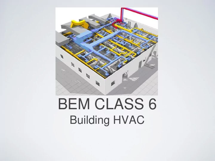
BEM CLASS 6 Building HVAC Role of HVAC Equipment To maintain a - - PowerPoint PPT Presentation
BEM CLASS 6 Building HVAC Role of HVAC Equipment To maintain a comfortable and healthy indoor environment for occupants by controlling the Temperature Moisture Content (humidity) Air Quality Air Circulation Goals Gain an
To maintain a comfortable and healthy indoor environment for occupants by controlling the
Gain an understanding of:
Conditioning Systems
Components
About How They Operate
Example: Window AC
from a room Changes from liquid to gas
moves to the Condenser
rejected to the environment and allowed to expand and change from gas back to a liquid
room is cooled to the desired set point
These “unitary systems” are very common in residential buildings New York City. They Require no distribution network (ducts) By their nature, they are individually controlled and not connected to other building operations. Though not used in Modern Commercial buildings the core cooling process (DX vapor compression cooling cycle) is used in more sophisticated air-handling applications, heat pump systems and large chillers.
Single-duct Constant volume Multi-zone, variable-air volume (VAV) Multi-zone with re-heat Dual-duct systems also possible but uncommon
8
humidification required by the zone(s)
systems)
system (AHU) or locally at a specific zone (Reheat)
and variable volume categories
(enthalpy) difference between supply and room air
9
Single zone Multiple-zone reheat Bypass VAV
Throttling Fan-powered Reheat Induction Variable diffusers
10
at the terminal device
systems?) vary flow rate
Single zone (“dual duct”)
Constant volume Variable air volume Dual conduit
Multizone
Constant volume Variable air volume Three-deck multizone
temperature resets, energy recovery
zones
13
save fan energy (fan energy proportional to flow rate cubed)
solar heating
to each
bound of VAV flow rate
flow rate
heating
and then adds reheat (or uses terminal device)
water distribution network. Ventilation is handled separately and only a “Primary” stream of outside air is supplied to the space.
periods, similar to baseboard heating)
17
same basic principle, just a different fluid
building.
through the building to meet the cooling load.
air exchange (air-cooled) or to cooling towers (water cooled).
compression cooling cycles. Absorption chillers are used when an abundant source of waste heat exists
20