
SLIDE 1
1
Review
- Only one statement executes at time
- Scope
– Global – Function – Block
- Variable Access Rules
– Outer scope variables can be accessed from an inner scope – Inner scope variables cannot be accessed from an outer scope
- Lifetime
– Variables come in to existence at declaration – Variables go out of existence when the block exits
- Shadowing
– An inner scope variable with the same name as an outer scope variable, shadows (or hides) the outer scope variable from the inner scope. – Nevertheless, both variables exist, and are distinct.
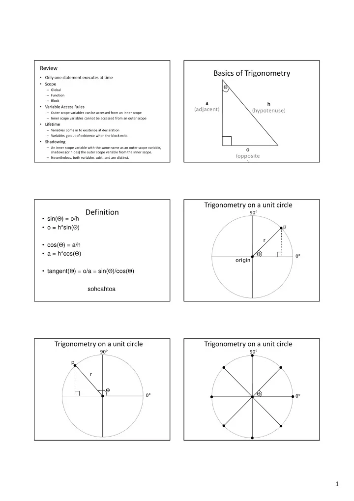
Basics of Trigonometry
Θ h (hypotenuse) a (adjacent)
- (opposite
)
Definition
- sin(Θ) = o/h
- o = h*sin(Θ)
- cos(Θ) = a/h
- a = h*cos(Θ)
- tangent(Θ) = o/a = sin(Θ)/cos(Θ)
sohcahtoa
Trigonometry on a unit circle
Θ r p
0° 90°
- rigin