
SLIDE 1
06-29-2005
Basics of Digital Logic Design
Presentation D CSE 675.02: Introduction to Computer Architecture
Gojko Babić
2
1 1 1 1 1 A and B B A 1 1 1 1 1 1 1 A or B B A
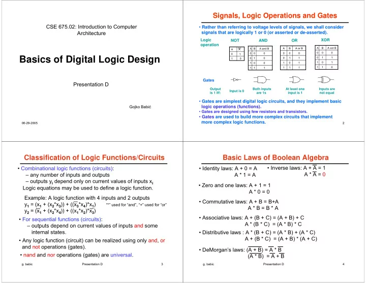
AND Logic
- peration
XOR OR NOT
Output is 1 iff: Input is 0 Both inputs are 1s At least one input is 1 Inputs are not equal
1 A A 1 1 1 1 1 1 1 A xor B B A
Signals, Logic Operations and Gates
- Rather than referring to voltage levels of signals, we shall consider
signals that are logically 1 or 0 (or asserted or de-asserted).
- Gates are simplest digital logic circuits, and they implement basic
logic operations (functions).
- Gates are designed using few resistors and transistors.
- Gates are used to build more complex circuits that implement
more complex logic functions.
Gates
- g. babic
Presentation D 3
Classification of Logic Functions/Circuits
- Combinational logic functions (circuits):
– any number of inputs and outputs – outputs yi depend only on current values of inputs xi
- For sequential functions (circuits):
– outputs depend on current values of inputs and some internal states.
- Any logic function (circuit) can be realized using only and, or
and not operations (gates).
- nand and nor operations (gates) are universal.
Example: A logic function with 4 inputs and 2 outputs y1 = (x1 + (x2*x3)) + ((x3*x4)*x1) “*” used for “and”, “+” used for “or” y2 = (x1 + (x2*x4)) + ((x1*x2)*x3) Logic equations may be used to define a logic function.
- g. babic
Presentation D 4
Basic Laws of Boolean Algebra
- Identity laws: A + 0 = A
A * 1 = A
- Inverse laws: A + A = 1
A * A = 0
- Zero and one laws: A + 1 = 1
A * 0 = 0
- Commutative laws: A + B = B+A
A * B = B * A
- Associative laws: A + (B + C) = (A + B) + C
A * (B * C) = (A * B) * C
- Distributive laws : A * (B + C) = (A * B) + (A * C)
A + (B * C) = (A + B) * (A + C)
- DeMorgan’s laws: (A + B) = A * B