
SLIDE 1
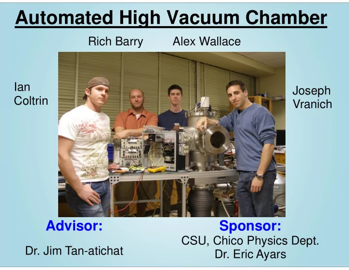
Automated High Vacuum Chamber
Advisor:
- Dr. Jim Tan-atichat
Sponsor:
CSU, Chico Physics Dept.
- Dr. Eric Ayars
Ian Coltrin Rich Barry Alex Wallace Joseph Vranich
Automated High Vacuum Chamber Rich Barry Alex Wallace Ian Joseph - - PowerPoint PPT Presentation
Automated High Vacuum Chamber Rich Barry Alex Wallace Ian Joseph Coltrin Vranich Advisor: Sponsor: CSU, Chico Physics Dept. Dr. Jim Tan-atichat Dr. Eric Ayars Background and Need Need Statement: The CSU, Chico Physics Department needs a
CSU, Chico Physics Dept.
Ian Coltrin Rich Barry Alex Wallace Joseph Vranich
Need Statement: The CSU, Chico Physics Department needs a vacuum chamber to perform a greater variety of experiments for students and faculty alike. Goal Statement: Design, build, and test a vacuum chamber that achieves high vacuum made with parts already donated.
Requirement Engineering Specification Metric Method/Device Target Condition High Vacuum Pressure Torr High Vacuum Pressure Gage 10-6 -10-7 Torr Maintained for at least 3 hrs.
Diameter reduction
interface screenshot
Wasteful
Potential for bad gauge reading? Non-issue
All chamber components cleaned with Acetone and Isopropyl
Once under vacuum, all gaskets compress and seal tightly
Possible Double Port Attachments Actual Configuration
during test runs
development
"Software in the Loop" Vacuum Control 1.0 Basic control state machine Vacuum Control 2.0 Correct pumping sequence User interfacing "Hardware in the Loop" Vacuum Control 3.0 & 3.1 Sensor interfacing I/O Restructuring Vacuum Control 4.0 Statistical smoothing of sensory data Error handling
vacuum RS-485 Interfaced via NI RS-485 to USB cable
Interfaced using BoB A/D Measures ATM to rough vacuum
Wheatstone bridge Measured by BoB A/D
use and greater modularity
Open loop cooling with temperature monitoring using 2 wire resistance thermistors. 1) 2) 3) 4)
pump
performance
system software
interfacing
and play operation
Checks: Autonomous valve operation Final Pressure Time to High Vacuum Correct user prompting
Requirements: Should Modifiable/Modular Support equipment for future experiments Usable by students Programmed in a familiar language Would be Nice Mobile Closed loop cooling
Component Price Overall Chamber $866 Foreline (Tubing, Feedthrough) $2234 Valves/Pneumatics $132 Misc (Cold Cap) $450 Total $3682
Component Price High vacuum gauge $972 PC $300 Breakout Device $99 Power Supplies $22 Misc (wire, terminals, etc.) $250 Total $1634
Mechanical Mechatronic
Component Price Chamber Pieces $14096 Foreline Connections $283.50 Valves $4029 Total $18408.50
Donated Total Purchased: $5316.00 Total Cost Overall: $23724.50
Design Mechanical Electrical Software Total Hours 416 441 260 1153 Cost $14,547.50 $15,421.80 $9,092.20 $40,320.40 Assembly and Test Mechanical Electrical Control System Total Hours 650 450 700 1352 Cost $22,730.47 $15,736.43 $24,479.00 $62,945.9
Fall 2009 Spring 2009
first attempt!
experiments
Craig Myers, Gino Giordano, Doug Reid from Duniway, Paul Young from Adixen, Jordan Lynn from NI, Dr. Ayars, Robert Kieth, Nick from FMS, Lisa Washburn, Dr. Gaffney, Dr. Ayars, Collier's Hardware staff, Mike Kellog From LAM who donated parts, Dale Word, etc...