
SLIDE 1
Fundamentals of Power Electronics Appendix 3: Averaged switch modeling
- f a CCM SEPIC
1
Appendix 3: Averaged switch modeling
- f a CCM SEPIC
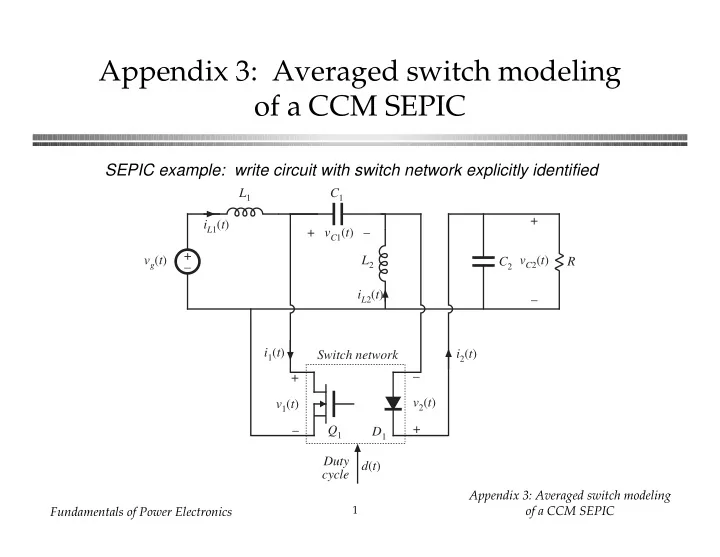
SEPIC example: write circuit with switch network explicitly identified
+ v1(t) – + – D1 L1 C2 Q1 C1 L2 R iL1(t) vg(t) Switch network iL2(t) + vC1(t) – + vC2(t) – – v2(t) + i1(t) i2(t) Duty cycle d(t)