
SLIDE 1
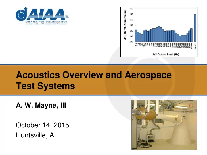
Acoustics Overview and Aerospace Test Systems
- A. W. Mayne, III
October 14, 2015 Huntsville, AL
Acoustics Overview and Aerospace Test Systems A. W. Mayne, III - - PowerPoint PPT Presentation
Acoustics Overview and Aerospace Test Systems A. W. Mayne, III October 14, 2015 Huntsville, AL 2 INTRODUCTION 3 What We Will Cover Basic Acoustic Concepts High-Intensity Acoustic Test Systems for Aerospace Applications
October 14, 2015 Huntsville, AL
2
What We Will Cover
3
A Few Acoustic Projects I Have Worked On
(Courtesy of INPE, Brazil)
REVERBERATION CHAMBER FOR TESTING SPACECRAFT
(Courtesy of NAL, India)
HIGH-FREQUENCY GAS JET NOISE SOURCE 10 HZ HORN AND NOISE SOURCE
(“Popular Mechanics”, p. 16, Aug 1995)
4
5
Acoustics in General
medium.
discuss small amplitude (linear), ideal gas acoustics.
speed characteristic of the medium (speed of sound).
and wavelength.
and some cannot.
6
Speed of Sound
a medium (ft/s, m/s, etc.)
square root of the absolute temperature of the gas.
T in degrees R, c in ft/s
T in degrees K, c in m/s
7
Sound Pressure
the ambient, undisturbed pressure
PEAK AMPLITUDE = 1.126 Pa AMBIENT PRESSURE
8
(100 Hz, 92 dB)
RMS Sound Pressure
average sound pressure of the acoustic wave (psi, Pa, etc.)
9
(100 Hz, 92 dB)
RMS AMPLITUDE = 1.126/√2 = 0.796 Pa AMBIENT PRESSURE (Ppeak = 1.126 Pa)
Wavelength
corresponding point on the following wave (feet, meters, etc.)
10
WAVELENGTH
WAVELENGTH
= 3.433 m
(100 Hz, 92 dB)
Frequency
3 CYCLES IN 0.03 s = 3/0.03 = 100 Hz CYCLE 1 CYCLE 2 CYCLE 3
11
(100 Hz, 92 dB)
Frequency Gas Temp. Speed of Sound Wavelength f T c = (γRT)^0.5 λ = c/f (Hz) (C) (m/s) (m) 100 air 20 343 3.433 100 H2 20 1305 13.052 15000 air 20 343 0.023 Wavelength-Frequency Relationship
12
Sound Pressure Level (LP or SPL)
intensity level, etc.
pressure level, but it will generally be stated simply as “85 dB”.
13
SPL Spectrum OVERALL SOUND PRESSURE LEVEL: THE LOG SUM OF THE SPL’S IN ALL BANDS SPL IN EACH 1/3 OCTAVE BAND
14
1/3 OCTAVE BAND CENTER FREQUENCIES
(Space Shuttle STS-1 Launch Spectrum, T-6 s to T+12 s)
Microphones for Test and Measurement
and convert them into an electrical signal.
condenser and piezoelectric.
free field, random-incidence field.
and tolerance, frequency range, cable length, standards, existing instrumentation.
15
Array of Microphones in a Reverberant Test Chamber
TRIPOD COAXIAL MICROPHONE CABLES LEAD OUTSIDE THE TEST CHAMBER TO THE MICROPHONE POWER SUPPLY, SPECTRUM CONTROLLER, & DATA ACQUISITION SYSTEM MICROPHONE & CLAMP SUPPORT
(Courtesy of INPE, Brazil)
16
Reflection and Boundary Absorption INCIDENT WAVE, Ii REFLECTED WAVE Ir =(1-α)Ii TRANSMITTED ENERGY It =αIi
surfaces like a wall
is reduced according to the absorption coefficient, “α” (alpha)
material, surface, angle, and frequency
(SOME ENERGY IS ABSORBED IN THE WALL; SOME IS RADIATED FROM THE FAR SIDE) WALL OR OTHER BOUNDING SURFACE
17
Absorption in Air (or Other Gases)
through air.
about 1000 Hz).
18
Examples of Absorption in Air (Gas Absorption Only) 500 Hz, 20 C, 20% RH AND 50% RH (ALMOST THE SAME)
19
Nonlinear Behavior
analyzed under the assumption of linear behavior:
such as the distortion of an acoustic wave at very high sound pressures.
20
Distortion of a High-Intensity Sine Wave (165 dB) NEAR THE SOURCE, THERE IS A SINE WAVE (A SINGLE FREQUENCY) 27.6 FT DOWNSTREAM, THERE IS A SAWTOOTH WAVE (LOTS OF HIGHER FREQUENCIES)
(Miller, “Development of a Wide-Band, Ten Kilowatt Noise Source,” IEST Proceedings, 1967)
21
22
Acoustic Test Levels for Rockets and Aircraft (A/C)
Vehicle Location OASPL (dB) Transport A/C1 Away from jet exhausts 130.0 Transport A/C1 Internal, close to jet exhausts 140.0 Delta IV Rocket2 Inside 5-m payload fairing (Acceptance Level) 140.6 High-Performance A/C1 Away from jet exhausts 145.0 Delta IV Rocket2 Inside 5-m composite payload fairing (Qualification Level) 146.1 Med-Performance A/C1 Air-to-air missile on A/C 150.0 Hi-Performance A/C1 Inside nose cone 160.0 Hi-Performance A/C1 Air-to-air missile on A/C 165.0
1. MIL-STD-810G, “Environmental Engineering Considerations and Laboratory Tests,” Oct., 2008. 2. United Launch Alliance, “Delta IV Payload Planners Guide,” Sep., 2007.
23
Acoustic Test Requirements
24
Government Standard: MIL-STD-810G
(Ref. Method 515.6)
Commercial Standard: Delta IV Payload Planners Guide
(Ref. Section 4.2.3.3)
Common High-Intensity Acoustic Test Facilities
25
Large RATFs
spacecraft
built outside the US in the last 25 years
power
system
(Courtesy of INPE, Brazil)
26
Electropneumatic Noise Sources & Horns
(Courtesy of INPE, Brazil)
27
200 Hz HORN (NOT VISIBLE) WAS-3000 NOISE SOURCE (30 kW) 25 Hz HORN EPT-200 NOISE SOURCE (10 kW) GAS SUPPLY GAS SUPPLY
SMALL PWT LARGE PWT INITIAL HORN(S) ANECHOIC TERMINATION TEST SEGMENT NOISE SOURCE(S)
(Webb, Royal Aircraft Establishment Tech. Report No. 65170, Sep., 1965)
28
Array of Loudspeakers
(DFAT)
surrounds the test article
electropneumatic noise sources
(Courtesy of Orbital Sciences Corporation)
TEST ARTICLE LOUDSPEAKER ARRAY
29
30
TOWED SOURCE WIDE-BAND CALIBRATION SOURCE SUBMARINE MOUNTED SOURCE
Some Types of Underwater Systems
( Courtesy of Data Physics Corp.)
31
projector
projector
Moving-Coil Underwater Projectors (Hydrosounders)
( Courtesy of Data Physics Corp.)
32
Towed Systems (Towfish) TOWING ATTACHMENT DEPRESSER MONITOR HYDROPHONE TAIL FIN UW350 PRESSURE VESSEL
33
HIGH-FREQUENCY SPHERICAL TRANSDUCERS
( Courtesy of Data Physics Corp.)
Calibration Systems
patterns
Kingdom and in Korea
for easy deployment
( Courtesy of Data Physics Corp.)
34
UW350 TYPE B RING TRANSDUCERS SPHERICAL TRANSDUCERS
35